
Liquid ejection apparatus and method of controlling the same

a technology of liquid ejection and liquid droplets, which is applied in printing and other directions, can solve the problems of deviation of direction, failure of ejection of ink droplets, and occurrence of such ejection faults, and achieve the effect of improving the ejection efficiency of viscous liquid

Active Publication Date: 2005-09-29
SEIKO EPSON CORP
View PDF1 Cites 22 Cited by
  • Summary
  • Abstract
  • Description
  • Claims
  • Application Information

AI Technical Summary

Benefits of technology

[0010] It is therefore an object of the invention to improve the ejection efficiency of viscous liquid in a flushing operation.
[0021] With the above configuration, the liquid in the nozzle orifice in one of the first and second groups can be agitated by residual vibrations while the nozzle orifice in the other one of the first and second groups is subjected to the flushing operation. Accordingly, unnecessary liquid such as viscous liquid can be ejected more efficiently. Since the unnecessary liquid ejection can thus be obtained adequately with a lower flushing number, the time required for the flushing operation can be shortened to speed up the overall operations of the apparatus and lower the consumption amount of liquid during the flushing operation.
[0022] Further, contributions can be made to improvement of the unnecessary liquid ejection while making one resting period (duration of the non-flushing state) as short as possible and yet preventing liquid from being viscous.
[0026] With this configuration, simultaneous flushing of adjacent nozzle arrays is avoided. Accordingly, efficient ejection of unnecessary liquid can be carried out while restraining the generation of an updraft at regions between adjacent nozzle arrays and thereby preventing the problem of a part of the ejected liquid droplets becoming a mist and riding on the updraft and thereby becoming attached to the nozzle formation face of the liquid ejection head.

Problems solved by technology

Thus at nozzle orifices, with which the non-ejecting state is sustained during the recording operation, the solvent gradually evaporates and the ink becomes viscous with the elapse of the non-ejecting time, causing the occurrence of such ejection faults, as deviation of the direction of flight of ink droplets, failure of ejection of ink droplets, etc.
However, in a case where the recording operation is not carried out for a long period of time, the solvent volatilizes and the ink becomes viscous gradually even in this sealed state, causing ejection faults, such as failure of ejection of ink droplets, especially the smallest ink droplets among the ink droplets ejectable by the recording head, to occur at the start of a subsequent recording operation.
However, if the flushing operation is simply shortened, flushing of an amount adequate for preventing ejection faults cannot be carried out.
Also, especially in the case where, after the activation of a printer following a state in which the printer has not been used for a long period of time and a flushing operation is carried out prior to a recording operation, there is a high possibility that viscous ink or solidified ink exists at the vicinity of the nozzle orifices, and since in this case, a large flushing number (number of ejected ink droplets during the flushing operation) is required for ejection of the viscous ink, solidified ink, or other unnecessary ink, much time and a large amount of ink are consumed correspondingly.

Method used


Image

  • Liquid ejection apparatus and method of controlling the same
  • Liquid ejection apparatus and method of controlling the same
  • Liquid ejection apparatus and method of controlling the same

Examples


Embodiment Construction

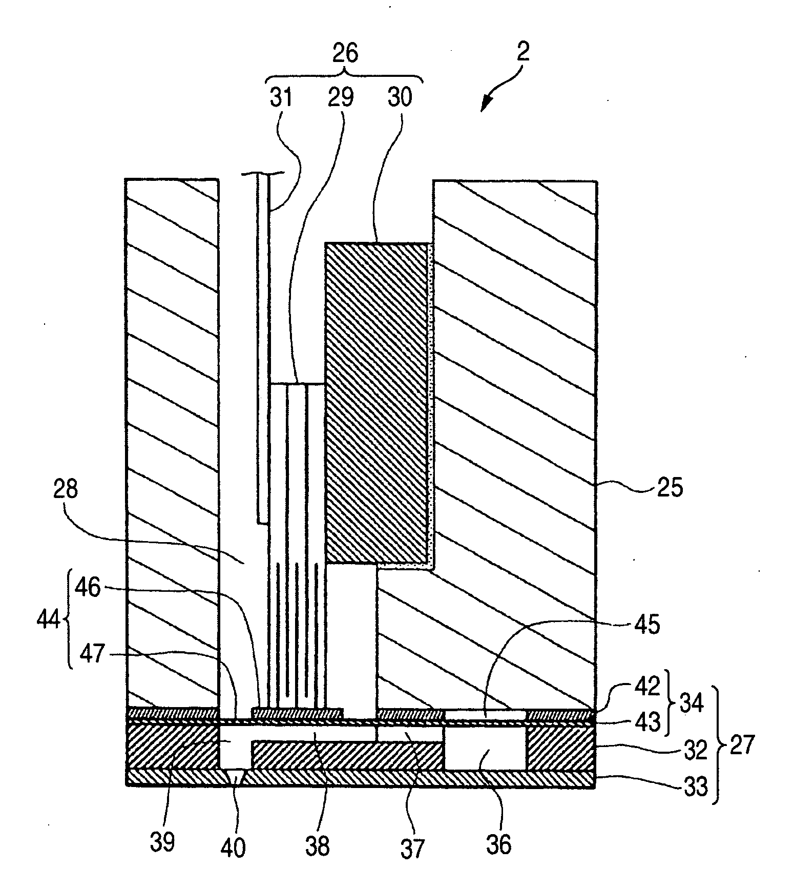
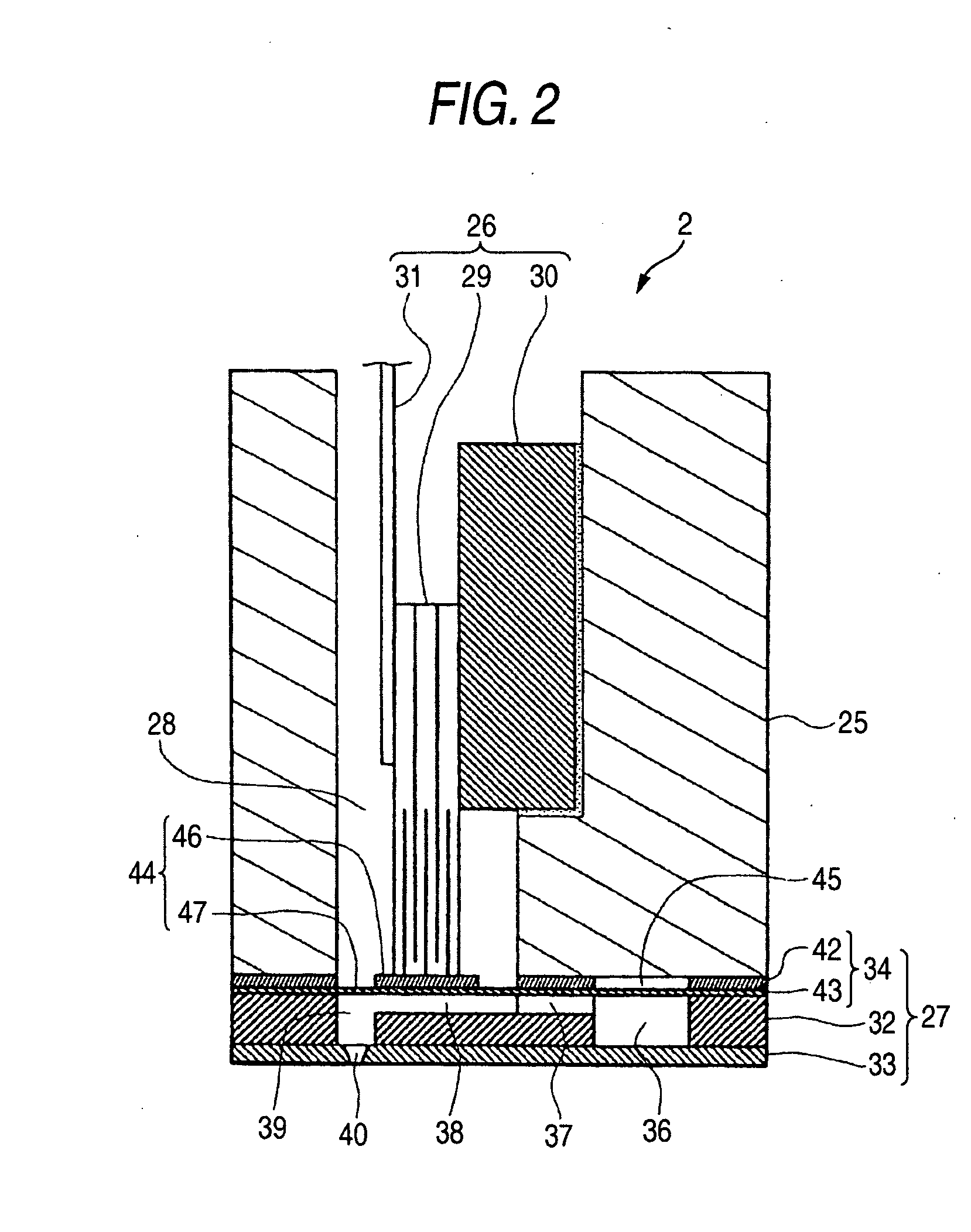
[0035] Embodiments of the invention will be described below in detail with reference to the accompanying drawings. An ink jet printer (abbreviated hereinafter as “printer”) will be described as an example of the liquid ejection apparatus of the invention.

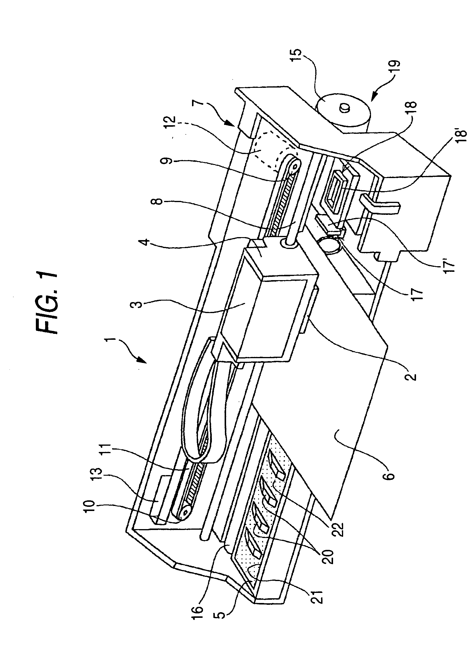
[0036] A printer 1, illustrated in FIG. 1 is generally arranged by being equipped with a carriage 4 which carries a recording head 2 adapted to eject ink in the form of ink droplets and mounted thereto and an, ink cartridge 3 mounted detachably thereto; a platen 5 disposed below the recording head 2; a carriage driving mechanism 7 for moving the recording head 2 (carriage 4) in the width direction of recording paper 6; and a paper feeding mechanism 19 for conveying the recording paper 6 in a paper feeding direction, which is a direction orthogonal to the head moving direction. Here, the paper width direction is referred as a primary scanning direction, and the paper feeding direction is referred a secondary scanning direction.

[003...


PUM


Abstract

A liquid ejection head is caused to eject liquid droplets at a region where no target medium is placed, such that such that a first prescribed number of liquid droplets are flushed from each of the nozzle orifices in the nozzle arrays of the first group, and a second prescribed number of liquid droplets are flushed from each of the nozzle orifices in the nozzle arrays of the second group. At least a part of the first prescribed number of liquid droplets and at least a part of the second prescribed number of liquid droplets are flushed by alternately performing a first unit operation for flushing a third prescribed number of liquid droplets which is smaller than the first prescribed number and a second unit operation for flushing a fourth prescribed number of liquid droplets which is smaller than the second prescribed number.

Description

BACKGROUND OF THE INVENTION [0001] This invention relates to a liquid ejection apparatus such as an ink jet printer, and a method of controlling the same. This invention particularly relates to a liquid ejection apparatus capable of performing a flushing operation for forcibly ejecting liquid droplets from nozzle orifices, and a method for controlling such a liquid ejection apparatus. [0002] A liquid ejection apparatus is equipped with a liquid ejection head, which can eject liquid in the form of droplets. As a representative example of this liquid ejection apparatus, there is an image recording apparatus such as an ink jet printer which ejects ink droplets onto recording paper, etc., as an ejection target to form dots thereon and thereby carry out recording. Also besides such an image recording apparatus, liquid ejection apparatuses are being applied to various manufacturing apparatuses in recent years. For example, with a display manufacturing apparatus for a liquid crystal displa...

Claims


Application Information

Patent Timeline
IPC IPC(8): B41J2/175B41J2/165B41J2/205
CPCB41J2/16526
Inventor AKASE, TAKASHIKIMURA, MASAHIRO
Owner SEIKO EPSON CORP
Learn More