
Clutch assembly with smooth engagement

Inactive Publication Date: 2005-09-29
ZF MERITOR L L C
View PDF10 Cites 12 Cited by
  • Summary
  • Abstract
  • Description
  • Claims
  • Application Information

AI Technical Summary

Benefits of technology

[0009] In one disclosed embodiment, the reference points are monitored over time and saved in long-term memory. The clutch engagement rate is modified or updated based on changes in the reference points. This provides for more consistent responsiveness and performance as clutch components wear.
[0010] In one disclosed embodiment, the controller utilizes the reference points to determine varying engagement rates for optimizing responsiveness and for optimizing performance. By determining the reference points for torque transfer and clutch lockup, the controller can approach desired engagement and disengagement points at a high rate of speed to improve response. The controller automatically changes the rate of speed once the clutch is operating in the desired range to improve operating comfort and performance.

Problems solved by technology

One problem that has not been fully addressed relates to clutch actuation characteristics.
Traditionally, clutch systems have variable actuation characteristics that result from manufacturing, installation, wear, and environmental factors.
However, this is not practical as the process would be expensive and time consuming.
Further, the solution does not address the problem of component wear over time.
This solution is also unsatisfactory because neither comfort nor response is fully optimized for the system, as the ramped rate merely attempts to minimize the trade-off effects between comfort and responsiveness.

Method used


Image

  • Clutch assembly with smooth engagement
  • Clutch assembly with smooth engagement

Examples


Embodiment Construction

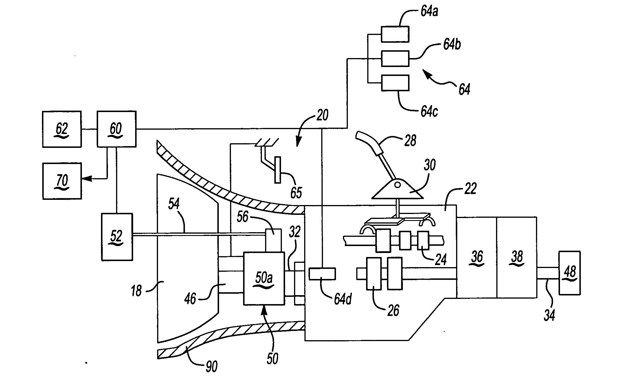
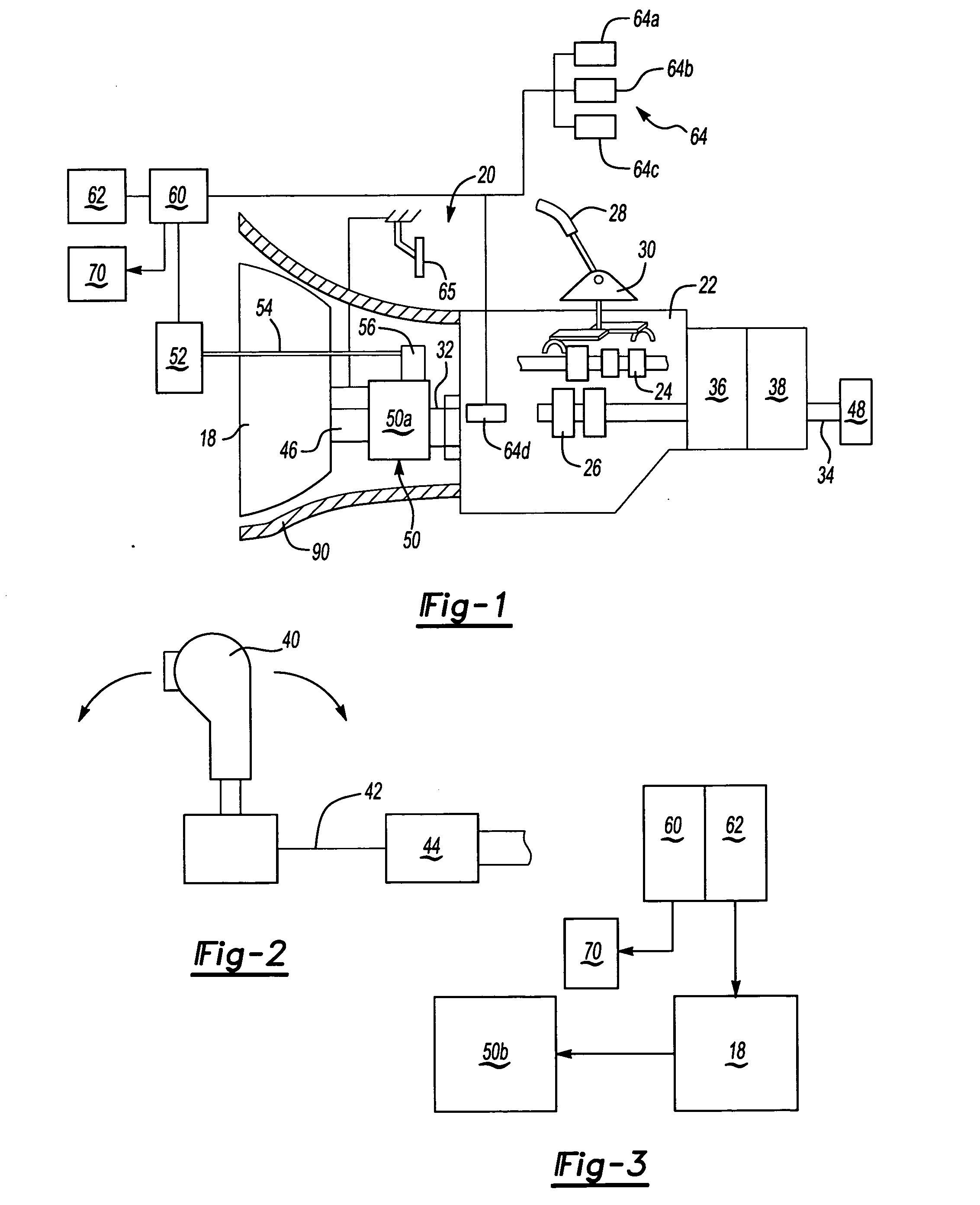
[0016]FIG. 1 diagrammatically illustrates an engine 18 and a transmission system 20 including a main gear box 22 that has a plurality of gear members 24 and 26. In the illustrated embodiment, a manually operable shift lever 28 is moveable about a pivot point 30 to manually, selectively engage one of the gear members 24 and 26 to achieve a desired gear ratio between a transmission input shaft 32 and a transmission output shaft 34.

[0017] The transmission system 20 can include a splitter gear assembly 36 to provide additional gear ratios between the ratios provided by gear members 24, 26 in the main gear box 22, or a range gear box 38 to provide additional gear ratios greater than the ratios provided by gear members 24, 26. The operation of range gear boxes 38 and splitter assemblies 36 are well known in the art and will not be discussed in detail. In some instances the use of a range gear box 38 or a splitter assembly 36 may not be necessary.

[0018] Additionally (as schematically ill...


PUM


Abstract

A clutch assembly controller monitors initiation points for torque transfer and clutch lockup to determine a clutch engagement rate. Engine output shaft and transmission input shaft speeds are monitored to determine the points at which the torque transfer and clutch lockup begin. These points are stored as reference points and are updated as the clutch wears over time. The clutch engagement rate is also modified over time as the reference points change. Further, the controller utilizes the reference points to approach the desired clutch engagement and disengagement points at a higher rate of speed to optimize responsiveness while automatically changing to a lower rate of speed once operating in the desired region of interest to optimize clutch operating performance and comfort.

Description

BACKGROUND OF THE INVENTION [0001] This application generally relates to vehicle clutch assemblies. More particularly, this invention relates to clutch assembly that automatically adjusts clutch engagement and disengagement response times to compensate for lag and wear. [0002] A variety of vehicle transmissions are available currently in the market. Some transmissions are automated and do not require operator input other than selecting a gear mode, for example, reverse or drive. Other transmissions are manual and require manual operation of a gear shift lever to manually move transmission components into selected gear ratios. In manual transmission configurations, a clutch assembly is needed to engage and disengage a transmission input shaft from the engine output shaft in order to move between gear ratios. This typically occurs by a manual actuation of a clutch pedal to eliminate the connection between the engine output shaft and the transmission input shaft. Manual clutch pedal ac...

Claims


Application Information

Patent Timeline
IPC IPC(8): F16D48/06
CPCF16D48/06F16D2500/10412F16D2500/1083F16D2500/3026F16D2500/30415F16D2500/30426F16D2500/7101F16D2500/30806F16D2500/30816F16D2500/50251F16D2500/5108F16D2500/5118F16D2500/70412F16D2500/3067
Inventor DEVORE, JAMES H.ALLEN, CHARLES E. JR.STURMER, WINFRIEDHEINZELMANN, KARL-FRITZRONGE, LUDGERDREIER, LOREN C.SAYMAN, ROBERT A.MUETZEL, RONALD P.ABUSAMRA, MUNEER
Owner ZF MERITOR L L C
Learn More