Eureka AIR delivers breakthrough ideas for toughest innovation challenges, trusted by R&D personnel around the world.

Quick release assembly

Active Publication Date: 2005-09-22
BODYPOINT
View PDF22 Cites 116 Cited by
  • Summary
  • Abstract
  • Description
  • Claims
  • Application Information

AI Technical Summary

Benefits of technology

[0013] In accordance with an embodiment, the release plate includes a lock which prevents undesired release of the body from the receiver. In an embodiment, the lock is re-positionable from a locked position to an unlocked position.

Problems solved by technology

A posterior pelvic tilt promotes rounding of the upper spine, which can lead to deformity.
Therefore, a rigidly stabilizing pelvic position is not desirable.
Currently available pelvic supports either do not control undesired pelvic movement, or lock the pelvis in a static, non-functional position.
Pivot movement is then limited by the amount of force the user can provide against the pivot mechanism and still attain pivoting movement.

Method used


Image

  • Quick release assembly
  • Quick release assembly
  • Quick release assembly

Examples


Embodiment Construction

[0029] In the following description, various embodiments of the present invention will be described. For purposes of explanation, specific configurations and details are set forth in order to provide a thorough understanding of the embodiments. However, it will also be apparent to one skilled in the art that the present invention may be practiced without the specific details. Furthermore, well-known features may be omitted or simplified in order not to obscure the embodiment being described. In addition, to the extent that orientations of the embodiments are described, such as “top,”“bottom,”“front,”“rear,”“right,” and the like, the orientations are to aid the reader in understanding the embodiment being described, and are not meant to be limiting.

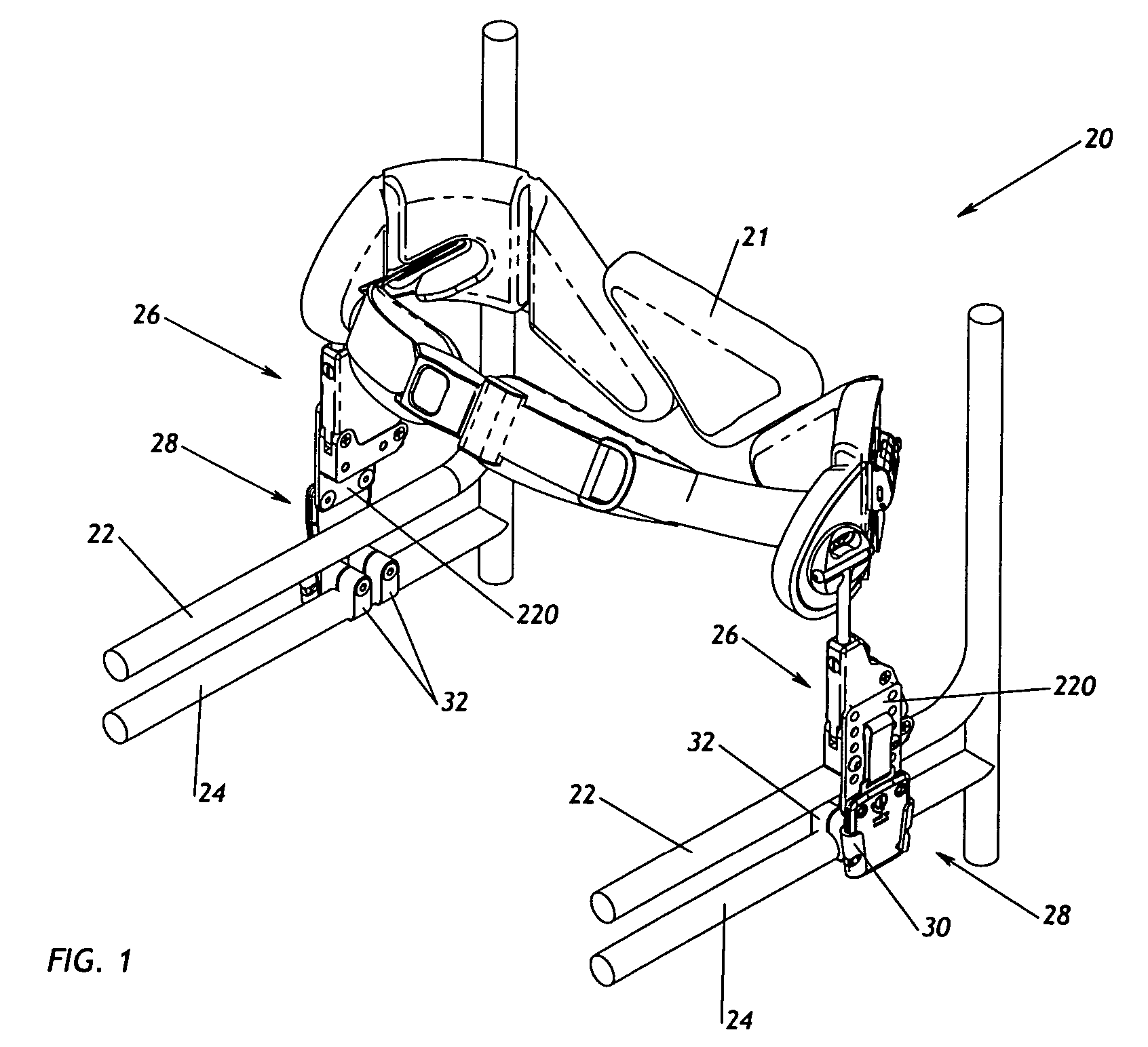
[0030] Referring now to the drawings, in which like reference numerals represent like parts throughout the several views, FIG. 1 shows a pelvic stabilization device 20 incorporating an embodiment of the invention. The pelvic stabilization...


PUM


Abstract

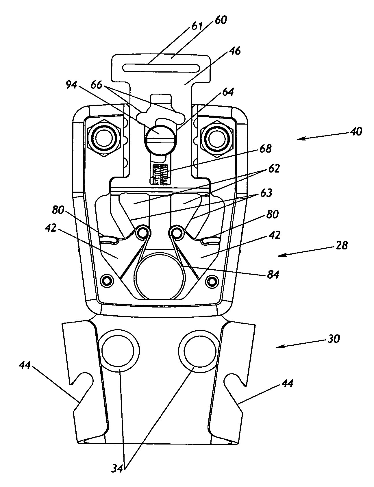
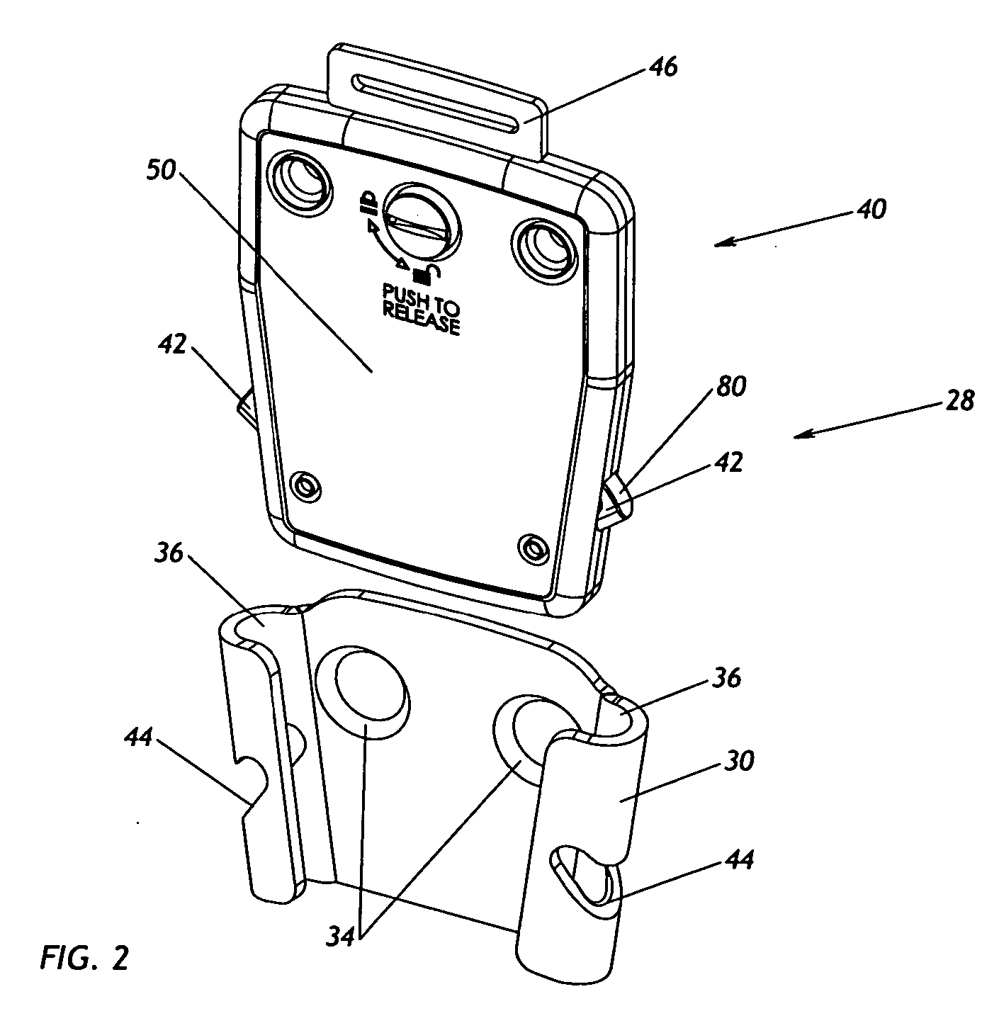
A pivoting side mount (26) which may used, for example, to attach a pelvic stabilization device (21) to a wheelchair. The pivoting side mount (26) includes first and second pivot brackets (152, 150) that are rotatably connected to one another and a spring (154), such as a rubber spring, for limiting the rotating movement of the two brackets relative to one another. A quick release assembly (28) is also provided. The quick release assembly (28) includes a receiver (30) and a body (40) that fits into the receiver. The body (40) includes one or more latches (42) that are biased outward and that snap into notches (44) in the receiver (30) when the body (40) is placed in the receiver (30). A release plate (46) is provided for releasing the latch or latches (42) from the notches (44).

Description

REFERENCE TO RELATED APPLICATION [0001] This patent application claims priority to U.S. provisional Patent Application No. 60 / 554,195, filed Mar. 18, 2004, and entitled “PIVOTING SIDE MOUNT AND QUICK RELEASE ASSEMBLY FOR A PELVIC STABILIZATION DEVICE,” incorporated herein by reference.TECHNICAL FIELD OF THE INVENTION [0002] The present invention is directed to ambulatory support devices, and more specifically to a pelvic stabilization device. BACKGROUND OF THE INVENTION [0003] Maintaining a proper pelvic posture and providing stability through the pelvis are critical to overall sitting posture. Freedom of movement can be enhanced by achieving a stable base of support. The optimum position for the pelvis is a slight anterior tilt. An effective pelvic support will prevent the pelvis from tilting posteriorly. A posterior pelvic tilt promotes rounding of the upper spine, which can lead to deformity. For a pelvis which posteriorly tilts, the top of the pelvis must be blocked from moving ...

Claims


Application Information

Patent Timeline
IPC IPC(8): A44B11/25A44B11/26A61F5/01A61G5/10A61G5/12B60R21/00F16D1/00
CPCA44B11/2592A44B11/26A61F5/0193A61G5/10A61G5/12Y10T403/602A61G2210/10Y10T403/608Y10T403/604Y10T403/599Y10T403/593A61G7/1069Y10T292/0854Y10T292/1056Y10T292/1077
Inventor KOSH, MATTHEWTILDEN, JOHN N.
Owner BODYPOINT
Why Eureka
Eureka Blog
Learn More