
Microfluidic flow manipulation device

a technology of microfluidics and flow devices, applied in the direction of other chemical processes, instruments, process and machine control, etc., can solve the problems of reagent mixing, excessive mixing channels, and performance limitations,

Inactive Publication Date: 2005-09-22
JOHNSON TIMOTHY J +2
View PDF5 Cites 4 Cited by
  • Summary
  • Abstract
  • Description
  • Claims
  • Application Information

AI Technical Summary

Benefits of technology

[0010] The present invention overcomes the disadvantages and limitations of the prior art by providing a device and method for effectively mixing two confluent laminar reagents within a very short stream length. This is accomplished by passing the confluent laminar flows over a series of narrow wells that are angled across the width of the channel. The device and method may also be used to split incoming streams into multiple streams of equal or non-equal proportions. Additionally, the present invention may be used for the mixing of plugs of reagents while minimizing axial dispersion of the reagent plug.
[0014] The advantages of the present invention are that flows may be combined and mixed without the conventional long lengths of diffusive mixing. The device may be further adapted to create two or more streams of equal or non-equal proportions of reagents. The device may be adjusted to tune the mix of the flows by adding various wells at different orientations, depths, and with various electroosmotic mobility coatings, all of which may have a substantial effect on the performance of the present invention.

Problems solved by technology

Although microfluidic devices have been highly successful, several performance limitations exist, notably reagent mixing.
This approach may be acceptable for low flowrates, but high flowrates (>1 cm / s) or low analyte diffusion coefficients (>10−7 cm / s2) will require excessively long mixing channels.
The difficulty in rapidly mixing reagents results from the fact that the system is restricted to the laminar flow regime (Re<2000) and also because the feature sizes are too small (typically<100 μm) to incorporate conventional mixing mechanisms.
However, even a mixing length of 25% may still be unsuitable for some applications.
For very small fluidic passages, such devices are extremely fragile and difficult to manufacture.

Method used


Image

  • Microfluidic flow manipulation device
  • Microfluidic flow manipulation device
  • Microfluidic flow manipulation device

Examples


embodiment 100

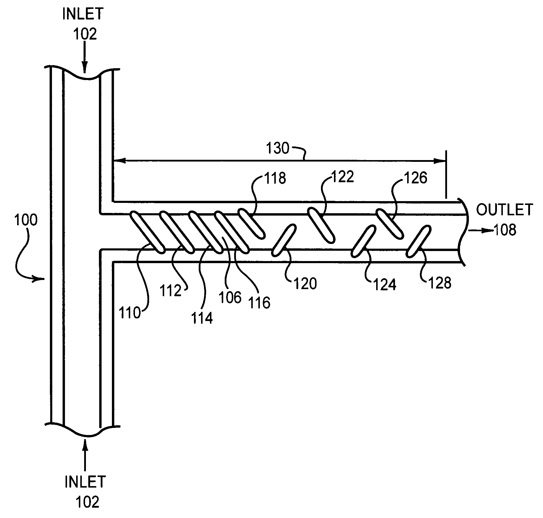
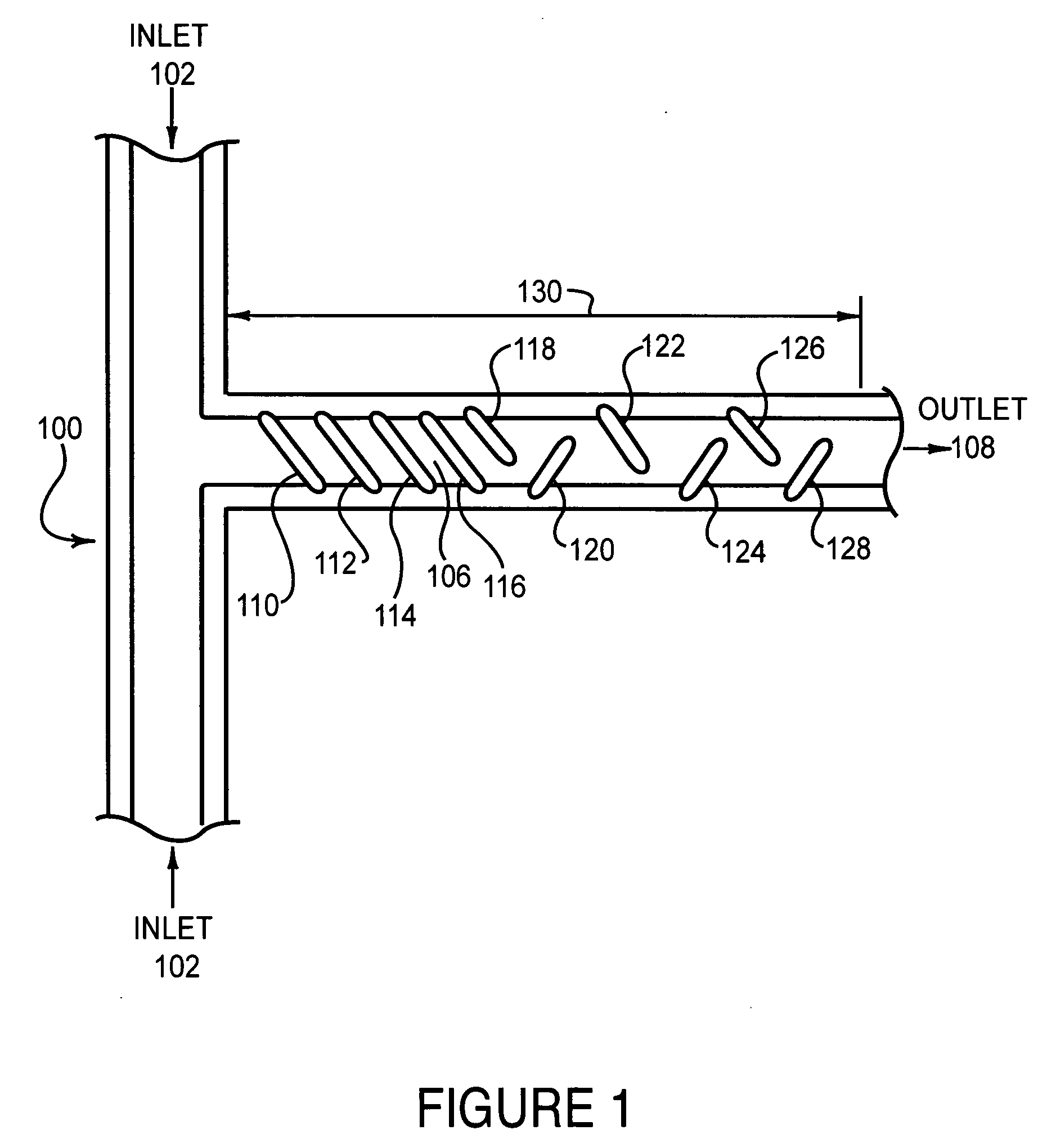
[0038]FIG. 1 illustrates an embodiment 100 of the present invention of a microfluidic mixer. Two inlet streams 102 and 104 are combined and mixed in the mixing region 106 to produce a mixed flow that exhausts out of the outlet 108. The mixing region 106 comprises several wells 110, 112, 114, 116, 118, 120, 122, 124, 126, and 128 that are recessed into the outlet 108.

first embodiment

[0039] In a first embodiment, the channels have a uniform, trapezoidal cross section, with the width at the top being 72 μm, depth 31 μm, and the width at the bottom being 28 μm. The wells 110, 112, 114, 116, 118, 120, 122, 124, 126, and 128 have a depth of 85 μm in the center of the well.

[0040] The wells 110, 112, 114, and 116 are parallel to each other and uniform in size. The wells are angled approximately 45 degrees from the axis of the outlet 108. The wells 118, 120, 122, 124, 126, and 128 are perpendicular to each other and are approximately 45 degrees from the axis of the outlet 108.

[0041] The flow of reagents through the embodiment 100 may be electrokinetic, electroosmotic, or pressure driven flow. Since the electroosmotic flow is a wall driven phenomenon based on the surface charge of the microchannel wall and on the local electric field, the fluid may enter and follow the contour of the wells, with the slanted well design used to induce lateral transport across the channe...

embodiment 600

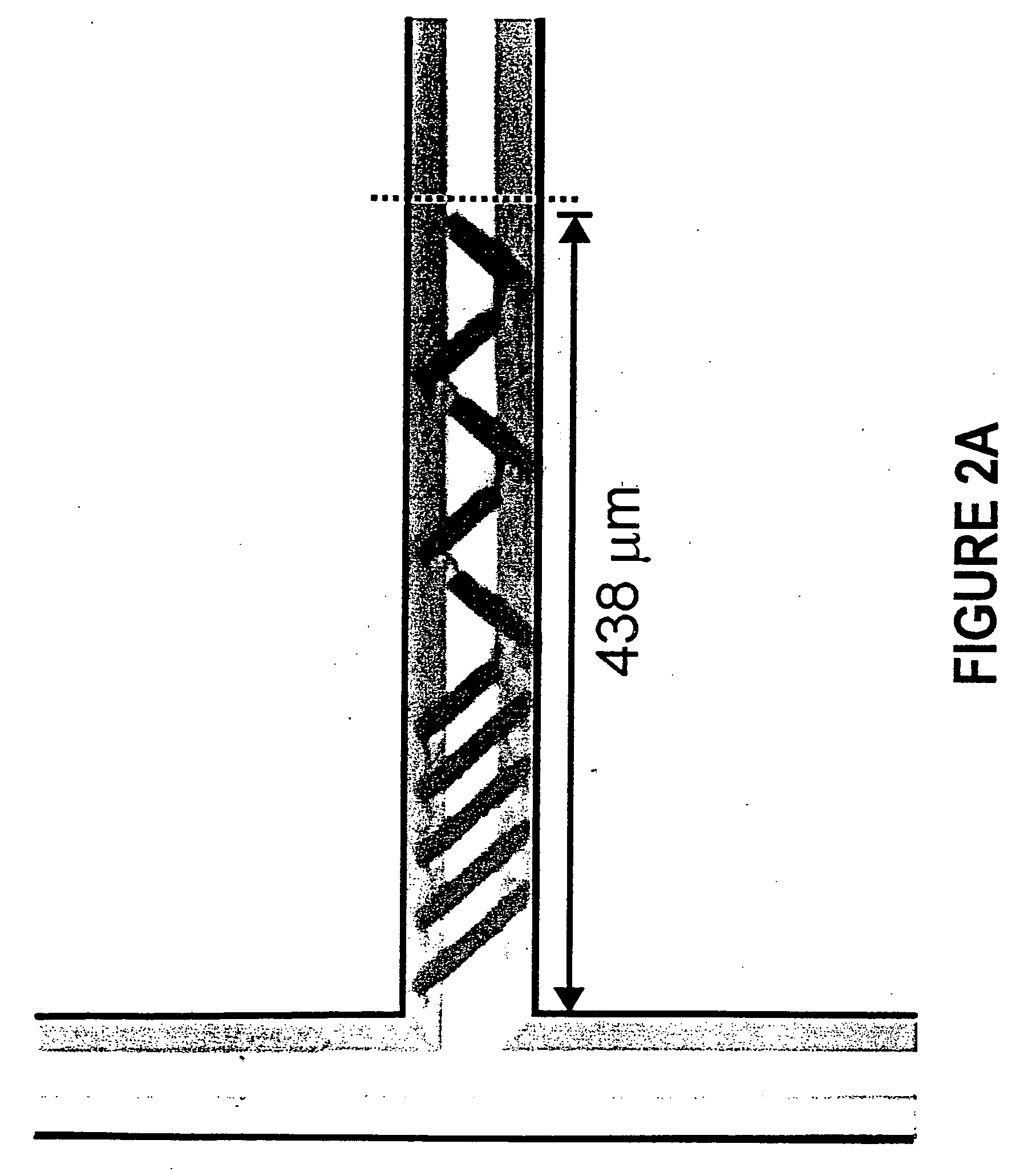
[0051]FIG. 7 is a white light microscopy image of an example of embodiment 600.

[0052]FIG. 8 is a graph that illustrates the degree of mixing of two reagents using embodiment 600 and an embodiment similar to embodiment 600 but with three wells instead of four. The experimental results of FIG. 8 show results for electroosmotic flow of 0.06 cm / s taken 183 μm from the point of confluence of the inlet flows. The horizontal axis is the position across the width of the outlet stream 608 and the vertical axis is the normalized intensity of Rhodamine B. The same experimental setup was used for the results of FIG. 3 as FIG. 8, with the differences being the configuration of the mixing region and the position of the measurements.

[0053] The curve 802 represents the mixing profile of the two inlet streams when no mixing wells are present. The curve 804 represents the perfect mixing of the two streams. The curve 806 represents the mixing profile for the electroosmotic flowrate of 0.06 cm / s and a...


PUM


Abstract

Disclosed is an apparatus and method for the mixing of two microfluidic channels wherein several wells are oriented diagonally across the width of a mixing channel. The device effectively mixes the confluent streams with electrokinetic flow, and to a lesser degree, with pressure driven flow. The device and method may be further adapted to split a pair of confluent streams into two or more streams of equal or non-equal concentrations of reactants. Further, under electrokinetic flow, the surfaces of said wells may be specially coated so that the differing electroosmotic mobility between the surfaces of the wells and the surfaces of the channel may increase the mixing efficiency. The device and method are applicable to the steady state mixing as well as the dynamic application of mixing a plug of reagent with a confluent stream.

Description

CROSS REFERENCE TO RELATED APPLICATIONS [0001] This application is based upon and claims priority to U.S. provisional application No. 60 / 323,509 entitled “MICROCHANNEL DESIGNS FOR MIXING AND SPLITTING MICROFLUIDIC STREAMS UNDER ELECTROKINETIC OR PRESSURE DRIVEN FLOW” filed Sep. 19, 2001 by Timothy J Johnson, David J Ross, and Laurie E Locascio, the entire disclosure is specifically incorporated herein by reference for all that it discloses and teaches.BACKGROUND OF THE INVENTION [0002] a. Field of the Invention [0003] The present invention pertains generally to microfluidic flow devices and specifically to mixers and splitters of microfluidic flow. [0004] b. Description of the Background [0005] The application of microfluidic analytical devices to chemical or biological assays has developed rapidly over the last decade. Although microfluidic devices have been highly successful, several performance limitations exist, notably reagent mixing. [0006] Most mixing devices rely on diffusiv...

Claims


Application Information

Patent Timeline
Patent Type & Authority Applications(United States)
IPC IPC(8): G05D7/06
CPCG05D7/0694Y10S366/03Y10T137/0318Y10T137/87652Y10T137/2224
Inventor JOHNSON, TIMOTHY J.ROSS, DAVID J.LOCASCIO, LAURIE E.
Owner JOHNSON TIMOTHY J
Learn More