Eureka AIR delivers breakthrough ideas for toughest innovation challenges, trusted by R&D personnel around the world.

Temperature detection device, temperature detection method, and computer-readable computer program product containing temperature detection program

a technology of temperature detection device and temperature detection method, which is applied in the direction of instruments, heat measurement, lighting and heating apparatus, etc., can solve the problems of increasing the size and cost of the temperature detection device in accompaniment with an increase in the number of parts, and achieve the effect of increasing the size and cost of the temperature detection device in accompaniment and increasing the number of parts

Inactive Publication Date: 2005-09-22
NISSAN MOTOR CO LTD
View PDF22 Cites 63 Cited by
  • Summary
  • Abstract
  • Description
  • Claims
  • Application Information

AI Technical Summary

Benefits of technology

[0005] However, if temperature detection elements and circuits are provided for semiconductor elements taken as subjects of temperature detection, this causes the size and cost of the temperature detection device to increase in accompaniment with an increase in the number of parts.
[0006] A temperature detection device in the invention includes a cooling medium temperature calculation device that calculates a temperature of a cooling medium in a cooling system in which a temperature detection subject driven at a prescribed driving ratio is cooled, and a temperature calculation device that calculates a temperature of the temperature detection subject based on drive information for the temperature detection subject, thermal resistance between the temperature detection subject and the cooling medium, and the temperature of the cooling medium calculated by the cooling medium temperature calculation device.
[0007] A temperature detection method in the invention includes the steps of calculating a temperature of a cooling medium in a cooling system in which a temperature detection subject driven at a prescribed driving ratio is cooled, and calculating temperature of a temperature detection subject based on drive information for the temperature detection subject, thermal resistance between the temperature detection subject and the cooling medium, and the temperature of the cooling medium.
[0008] A computer-readable computer program product in the invention contains a temperature detection program. The temperature detection program includes a process for calculating amount of heat occurring at a temperature detection subject, a process for calculating a temperature difference between the temperature detection subject and a cooling medium based on calculated amount of heat and thermal resistance between the temperature detection subject and the cooling medium in a cooling system in which the temperature detection subject is cooled, a process for excluding a transient response component of the cooling system from the calculated temperature difference, and a process for calculating the temperature of the temperature detection subject by adding the temperature difference from which the transient response component is excluded to the temperature of the cooling medium.

Problems solved by technology

However, if temperature detection elements and circuits are provided for semiconductor elements taken as subjects of temperature detection, this causes the size and cost of the temperature detection device to increase in accompaniment with an increase in the number of parts.

Method used


Image

  • Temperature detection device, temperature detection method, and computer-readable computer program product containing temperature detection program
  • Temperature detection device, temperature detection method, and computer-readable computer program product containing temperature detection program
  • Temperature detection device, temperature detection method, and computer-readable computer program product containing temperature detection program

Examples


first embodiment

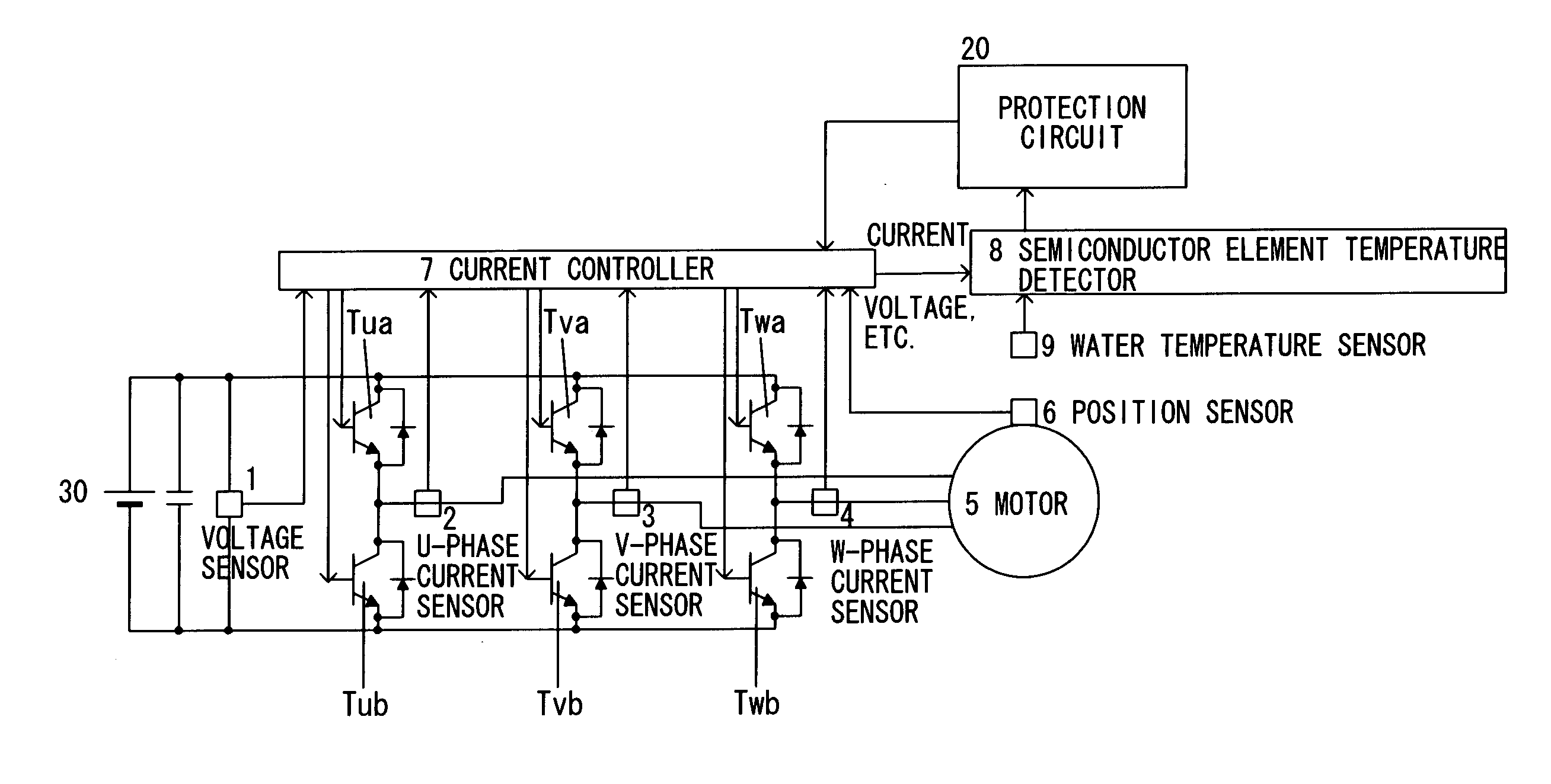
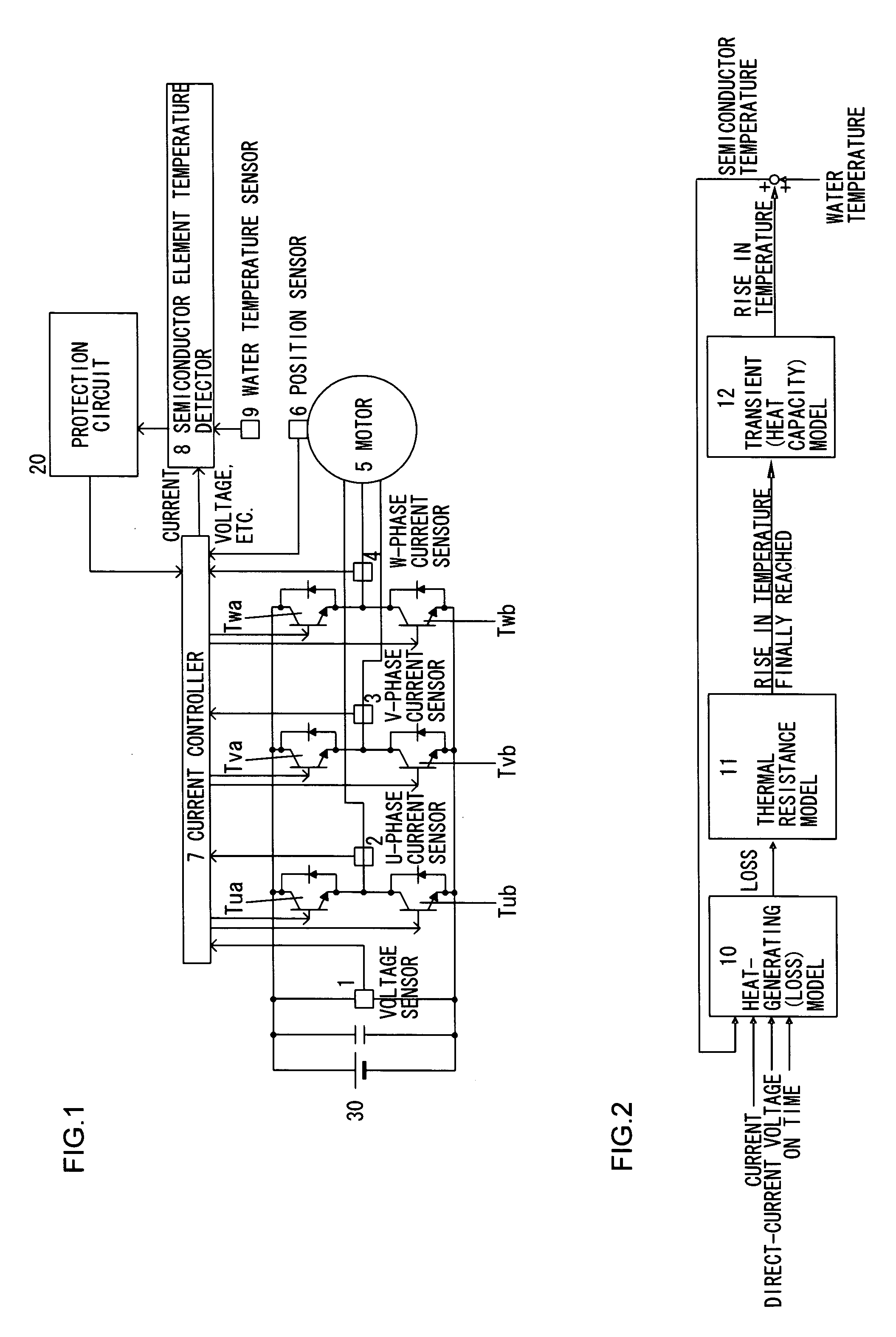
[0024]FIG. 1 is a view showing the essential parts of an electrical vehicle mounted with a temperature detection device in a first embodiment according to the present invention. In FIG. 1, a semiconductor module is configured from six insulated gate-type bipolar transistors (IGBT) Tua, Tub, Tva, Tvb, Twa and Twb. The semiconductor module composes an inverter for supplying electrical power to a motor 5 constituting a driver source for a vehicle. The direct current power of the battery 30 is converted to three-phase current power by switching each of the IGBTs at prescribed carrier frequencies. The three phases correspond to the U-phase, V-phase and W-phase, with IGBT Tua and Tub constituting the U-phase, IGBT Tva and Tvb constituting the V-phase, and IGBT Twa and Twb constituting the W-phase.

[0025] A voltage sensor 1 detects direct-current voltage applied to each phase of the semiconductor module. The detected voltage value is sent to a current controller 7. A U-phase current sensor...

second embodiment

[0065]FIG. 8 is a structural view describing the essential parts of an electrical vehicle mounted with a temperature detection device in a second embodiment according to the present invention. In FIG. 8, the same numeral numbers are assigned to components similar to those shown in FIG. 1 and the detailed explanation is omitted. The point of distinction with FIG. 1 is that a semiconductor element temperature detector 8A is provided in place of the semiconductor element temperature detector 8.

[0066]FIG. 9 is a block view illustrating a configuration for a semiconductor element temperature detector 8A. In FIG. 9, the semiconductor element temperature detector 8A includes a heat-generating (loss) model 10A, a thermal resistance model 11 and a transient (heat capacity) model 12. The semiconductor element temperature detector 8A detects the temperature of each IGBT at respective minimum operation periods (for example, 50 msecs) decided based on a time constant for the transient model. Th...

third embodiment

[0074] It is also possible for the temperature detection device in the first embodiment described above and the temperature detection device in the second embodiment to be switched according to the rotational speed of the motor 5 (rotational speed per unit time). In this case, temperature detection in the first embodiment is carried out in cases where the rotational speed of the motor 5 is lower than a prescribed speed, and temperature detection in the second embodiment is carried out when the rotational speed of the motor 5 is greater than a prescribed speed.

[0075] According to the third embodiment, regardless of the rotational speed of the motor 5, it is possible to apply the present inventions from low speeds to high speeds including cases where the motor becomes locked (rotational speed 0).


PUM

PropertyMeasurementUnit
transition model time constantaaaaaaaaaa
temperatureaaaaaaaaaa
temperature calculationaaaaaaaaaa

Abstract

Heating value P[W] generated at an IGBT is calculated, and a temperature difference ΔT′j [° C.] between a temperature Tw [° C.] of cooling water circulating in a cooling system and a temperature Tj [° C.] of an IGBT is calculated based on thermal resistance R [° C. / W] of the cooling system. A temperature rise ΔTj [° C.] with transient influences eliminated is then calculated based on the calculated temperature difference ΔT′j [° C.], and the temperature Tj [° C.] (=Tw [° C.]+ΔTj [° C.]) of the IGBT is calculated.

Description

BACKGROUND OF THE INVENTION [0001] 1. Field of the Invention [0002] The present invention relates to a temperature detection device that detects a temperature of a semiconductor module etc., a temperature detection method, and a computer-readable computer program product containing a temperature detection program. [0003] 2. Description of Related Art [0004] Power converters where inverters are made up of semiconductor switching elements etc. are used in electrical vehicles, etc. With this kind of electrical converter, it is necessary to detect the temperature of the semiconductor module in order to prevent the temperature of the semiconductor module from rapidly rising. In Japanese Laid Open Patent Publication No. 2000-134074, temperature detection diodes and temperature detection circuits are provided for each of the six semiconductor elements constituting a semiconductor module. SUMMARY OF THE INVENTION [0005] However, if temperature detection elements and circuits are provided fo...

Claims


Application Information

Patent Timeline
Patent Type & Authority Applications(United States)
IPC IPC(8): F25B1/00F25B15/00F25B49/00G01K11/00G01R31/26H02M7/48
CPCG01K7/425H02P29/02H02M1/32
Inventor KARIKOMI, TAKAAKIITO, KEN
Owner NISSAN MOTOR CO LTD
Why Eureka
Eureka Blog
Learn More