
Redundant wireless node network with coordinated receiver diversity

a wireless node network and receiver technology, applied in the field of wireless node networks, can solve the problems of adversely affecting the range and reliability of the network, the wireless link between the base station and the sensor is highly susceptible to shadowing and fading effects, and achieves the effects of improving the estimation process, increasing the signal-to-noise ratio (snr), and improving the estimation process

Inactive Publication Date: 2005-09-15
HONEYWELL INT INC
View PDF22 Cites 110 Cited by
  • Summary
  • Abstract
  • Description
  • Claims
  • Application Information

AI Technical Summary

Benefits of technology

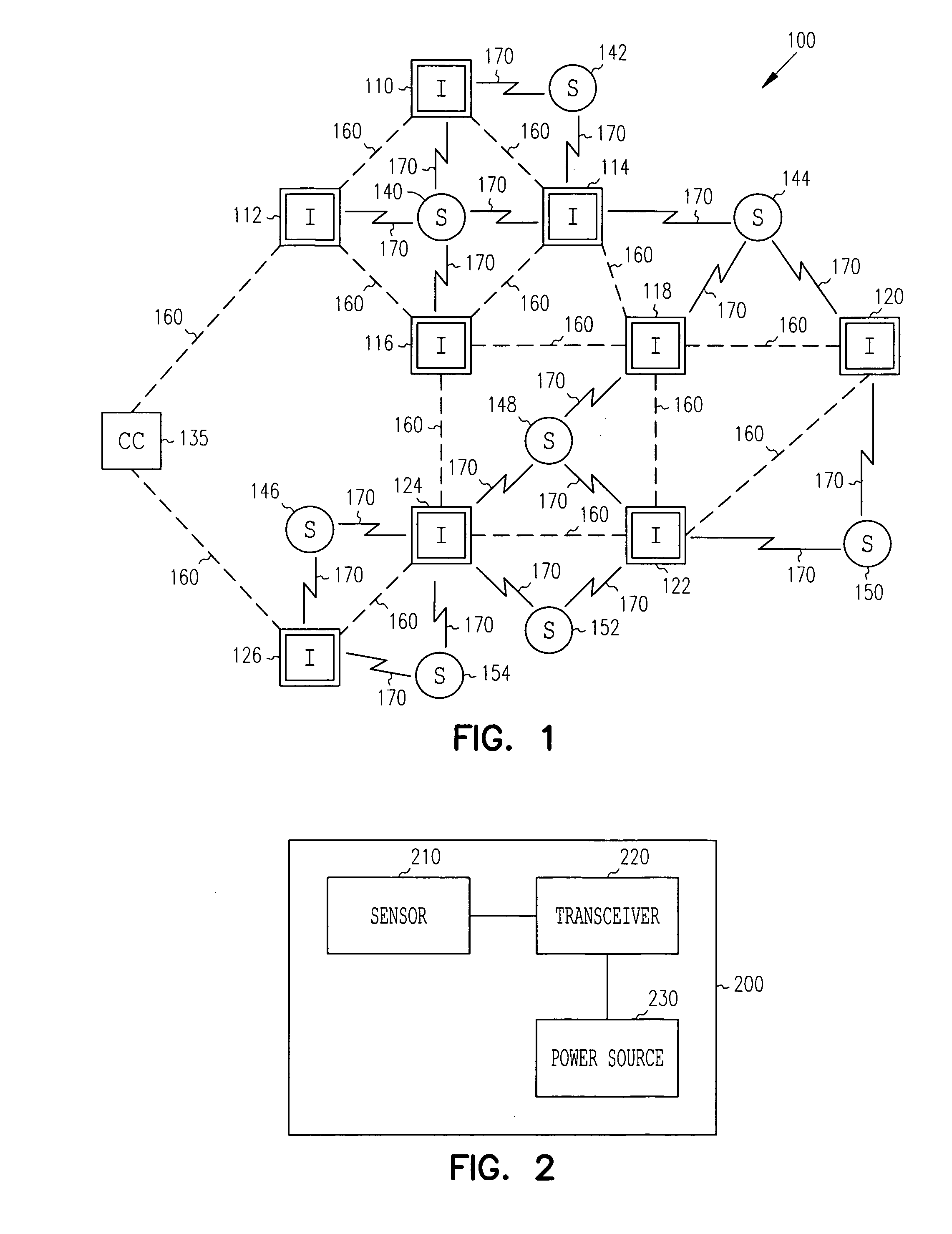
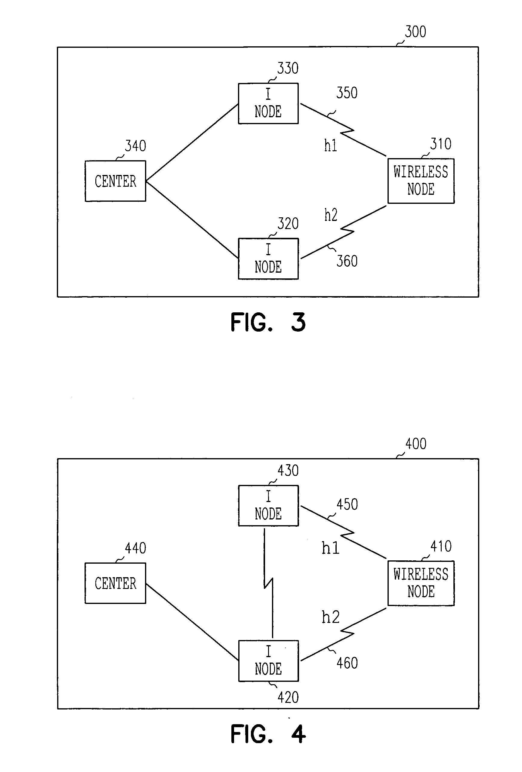
[0004] The use of wireless nodes, such as leaf nodes, provides great flexibility in leaf node placement, including places where wires cannot easily be run. Infrastructure nodes placement may be dictated by power availability in the case of line-powered wired infrastructure nodes. Line-powered or battery-powered wireless infrastructure nodes may also be utilized to provide greater flexibility in placement. The infrastructure nodes are placed by an installer to ensure redundant reception of leaf node transmissions, and thus diversity.
[0006] In one embodiment, maximal ratio combining is used to combine the received signals. The received signal at each infrastructure node can be viewed as the transmitted signal times a wireless channel coefficient plus a noise factor. To obtain a leaf node's signal estimation, two or more received signals are multiplied again by the complex conjugates of their respective wireless channel coefficients and added resulting in a combined signal which has an increased signal-to-noise ratio (SNR) thus improving the estimation process.
[0007] In further embodiments, other diversity techniques include equal gain combining, selection combining, switched combining and other techniques. The diversity combining techniques may be used to increase SNR and thus improve the signal estimation process.

Problems solved by technology

The base stations are placed throughout the network of sensors, and wireless links between the base stations and sensors are highly susceptible to shadowing and fading effects, especially in indoor wireless environments.
The effects adversely affect the range and reliability of the network.

Method used


Image

  • Redundant wireless node network with coordinated receiver diversity
  • Redundant wireless node network with coordinated receiver diversity
  • Redundant wireless node network with coordinated receiver diversity

Examples


Embodiment Construction

[0012] In the following description, reference is made to the accompanying drawings that form a part hereof, and in which is shown by way of illustration specific embodiments in which the invention may be practiced. These embodiments are described in sufficient detail to enable those skilled in the art to practice the invention, and it is to be understood that other embodiments may be utilized and that structural, logical and electrical changes may be made without departing from the scope of the present invention. The following description is, therefore, not to be taken in a limited sense, and the scope of the present invention is defined by the appended claims.

[0013] The functions or algorithms described herein are implemented in software or hardware, or a combination of software and hardware. The software comprises computer executable instructions stored on computer readable media such as memory or other type of storage devices. The term “computer readable media” is also used to ...


PUM


Abstract

A network of wireless nodes transmit electromagnetic signals, typically in the radio frequency (RF) mode, or at other frequencies. Multiple infrastructure nodes pick up the signals transmitted by each wireless node. The signals are combined to estimate the actual signal transmitted by the wireless node, such as a leaf node sensor. Many different diversity techniques may be used to combine the signals. In one embodiment, maximal ratio combining, equal gain combining, selection combining or switching combining is used to combine the signals.

Description

FIELD OF THE INVENTION [0001] The present invention relates to wireless node networks, and in particular to a redundant wireless node network with coordinated receiver diversity. BACKGROUND OF THE INVENTION [0002] Wireless nodes, such as sensors are networked via multiple base stations or access points that communicate with a central controller. The sensors operate at low power to conserve batteries, and to increase the time period in which batteries need to be replaced. This implies that the radio frequency (RF) signal generated by a sensor will have extremely low signal strength. The base stations are placed throughout the network of sensors, and wireless links between the base stations and sensors are highly susceptible to shadowing and fading effects, especially in indoor wireless environments. These effects are caused by RF propagation along multiple paths and by objects such as walls between the sensors and base stations. The effects adversely affect the range and reliability ...

Claims


Application Information

Patent Timeline
Patent Type & Authority Applications(United States)
IPC IPC(8): H04B7/08H04L12/28
CPCH04B7/084H04B7/0874H04B7/0857
Inventor BUDAMPATI, RAMAKRISHNA S.
Owner HONEYWELL INT INC
Learn More