
Plasma display device and driving method of plasma display panel

a technology of plasma display panel and display device, which is applied in the direction of instruments, television systems, and electrodes, can solve problems such as energy loss, and achieve the effect of improving discharge efficiency

Inactive Publication Date: 2005-09-15
SAMSUNG SDI CO LTD
View PDF10 Cites 7 Cited by
  • Summary
  • Abstract
  • Description
  • Claims
  • Application Information

AI Technical Summary

Benefits of technology

[0012] In accordance with the present invention a frequency of a sustain discharge pulse, is provided which is capable of improving a discharge efficiency when a partial pressure of Xe is high in a plasma display panel.

Problems solved by technology

As such, the ultraviolet ray can not be converted to a visible ray, which results in energy loss.

Method used


Image

  • Plasma display device and driving method of plasma display panel
  • Plasma display device and driving method of plasma display panel
  • Plasma display device and driving method of plasma display panel

Examples


Embodiment Construction

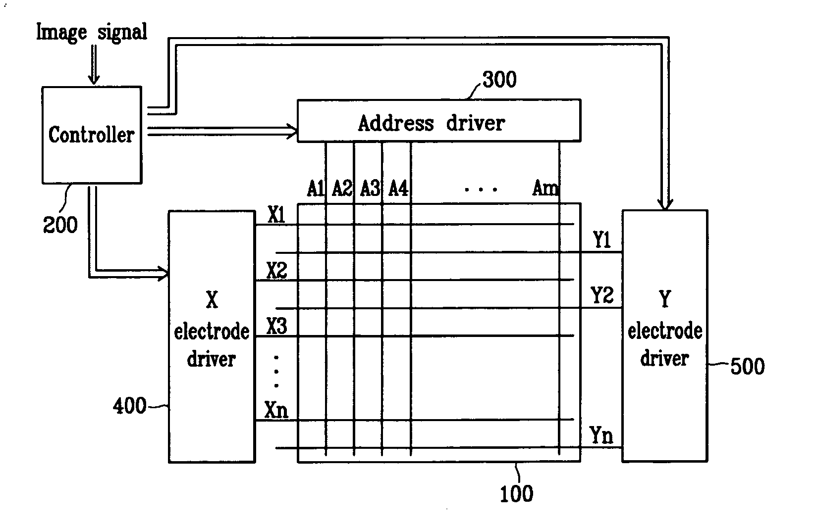
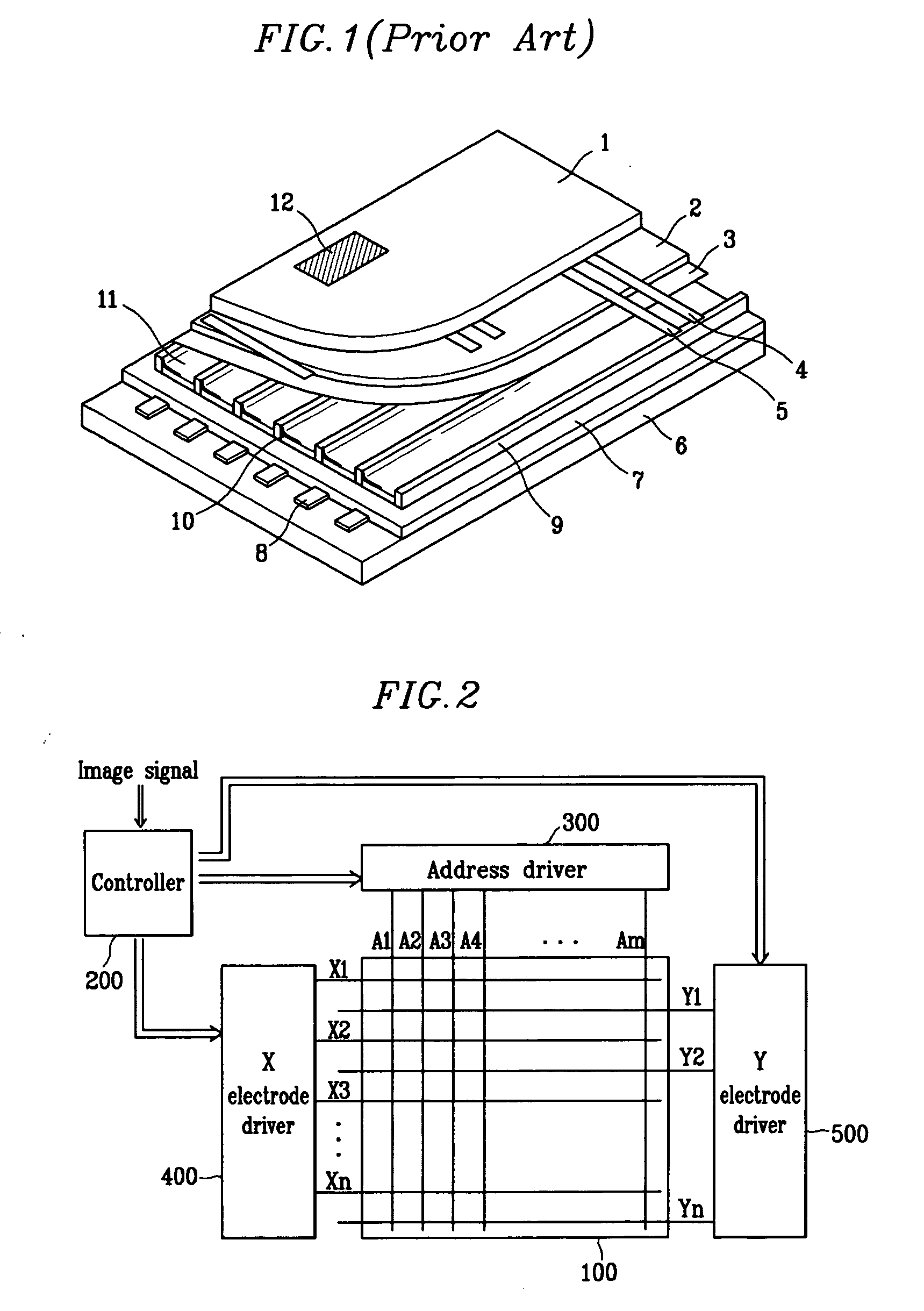
[0031] Referring to FIG. 2, the plasma display device includes a plasma display panel 100, a controller 200, an address electrode driver 300, a sustain electrode driver 400, and a scan electrode driver 500.

[0032] The plasma display panel 100 includes a plurality of address electrodes Al to Am (referred to as “A” electrodes hereinafter) extending in a column direction, and a plurality of sustain electrodes X1 to Xn (referred to as “X” electrodes hereinafter) and a plurality of scan electrodes Y1 to Yn (referred to as “Y” electrodes hereinafter) alternately extending in pairs in a row direction. The X electrodes X1 to Xn are formed corresponding to respective Y electrodes Y1 to Yn, and their ends are coupled in common. The plasma display panel 100 includes a substrate (not shown) on which the X and Y electrodes X1 to Xn and Y1 to Yn are arranged, and a substrate (not shown) on which the A electrodes A1 to Am are arranged. The two substrates face each other with a discharge space ther...


PUM


Abstract

A plasma display device, which is capable of improving a discharge efficiency of a plasma display panel by increasing a partial pressure of Xe. When the partial pressure of Xe is increased, a proportion of (Xe-Xe)* dimer emitting a 147 resonance line is higher than that of Xe* monomer emitting a 173 nm molecular beam. Particularly, when the partial pressure of Xe is above 10%, the discharge efficiency is improved by setting a frequency of a sustain discharge pulse applied to scan electrodes and sustain electrodes alternately during sustain period above 300 kHz.

Description

CROSS REFERENCE TO RELATED APPLICATION [0001] This application claims priority to and the benefit of Korean Patent Applications No. 10-2004-0016441 filed on Mar. 11, 2004 and No. 10-2004-0049324 filed on Jun. 29, 2004, in the Korean Intellectual Property Office, the contents of which are incorporated herein by reference. BACKGROUND OF THE INVENTION [0002] (a) Field of the Invention [0003] The present invention relates to a plasma display device and a method for driving a plasma display panel (PDP), and more particularly, to a frequency of a sustain discharge pulse applied to the PDP. [0004] (b) Description of the Related Art [0005] Plasma display devices are displays that use a PDP for displaying characters or images using plasma generated by gas discharge. The PDP includes, according to its size, more than several tens to millions of pixels (discharge cells) arranged in the form of a matrix. [0006]FIG. 1 is a perspective view illustrating part of a general PDP. Scan electrodes 4 an...

Claims


Application Information

Patent Timeline
Patent Type & Authority Applications(United States)
IPC IPC(8): G09G3/20G09G3/288G09G3/291G09G3/294G09G3/298H01J11/12H01J11/22H01J11/24H01J11/26H01J11/34H01J11/50H04N5/66
CPCG09G3/28G09G2310/066G09G2310/06G09G3/2942G09G3/294G09G3/296
Inventor YIM, SANG-HOONMIZUTA, TAKAHISA
Owner SAMSUNG SDI CO LTD
Learn More