
Cleaning tanks

a technology for cleaning tanks and tanks, applied in the field of cleaning tanks, can solve the problems of affecting the cleaning effect of the tank, affecting the cleaning effect, and accumulating, and achieve the effect of improving the coverage of the tank bottom

Inactive Publication Date: 2005-09-15
HEIL SCOTT +1
View PDF5 Cites 15 Cited by
  • Summary
  • Abstract
  • Description
  • Claims
  • Application Information

AI Technical Summary

Benefits of technology

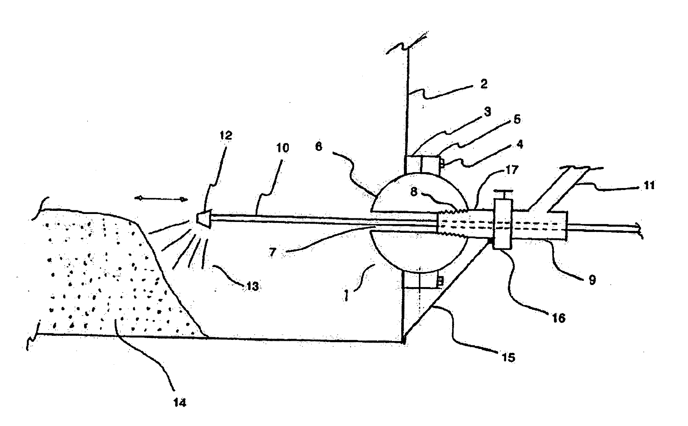
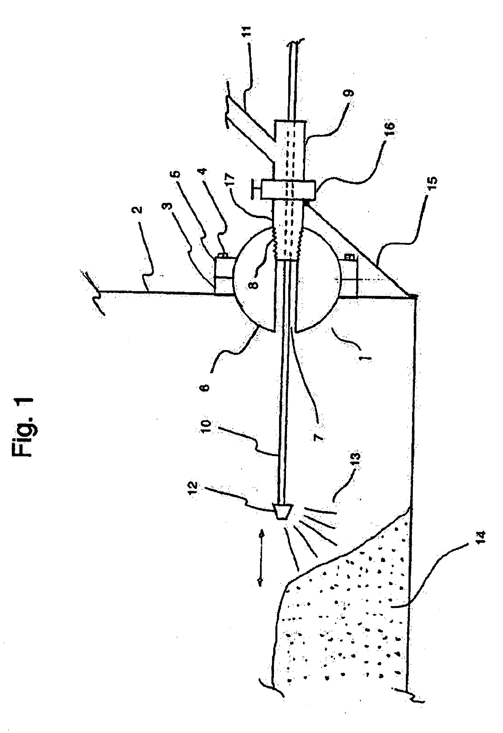
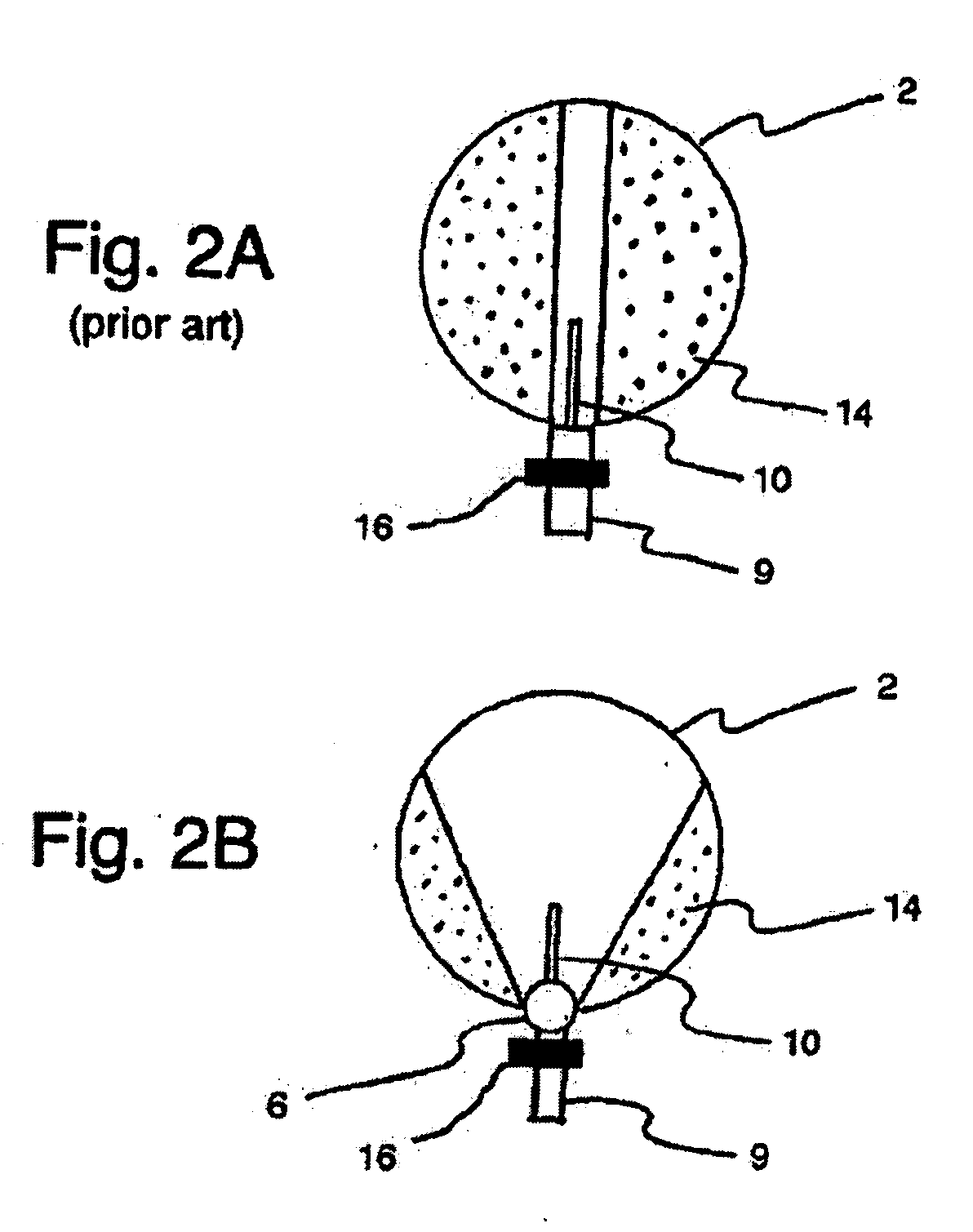
[0013] A high-pressure pressure wand is inserted through the swiveling body into the tank in a conventional manner. Horizontal movement of the swiveling body permits an operator to achieve improved coverage of the tank bottom during cleaning operations. The dislodged sediments can be sucked out of the tank in the space between the walls of the vacuum tube and the wand by a vacuum truck in a conventional manner.
[0014] The adapter apparatus of the invention provides for removal of a greater amount of the sediments in a tank, without the need to empty, decommission or disassemble the tank, and via a single port of entry into the tank. The adapter apparatus is simple and readily adapted to existing oil storage tanks. In construction of new tanks a swiveling body and swivel support device can be incorporated into a lower portion of the tank wall

Problems solved by technology

A problem with the storage of crude oil extracted from underground formations is that it commonly contains suspended sediments such as sand.
During the extraction process, these sediments remain in suspension however once the crude oil is in a storage tank, these sediments settle to the bottom of the tank, accumulating over time.
If allowed to accumulate, these sediments will eventually cause blockage of outlet ports in the tank through which the oil is normally removed.
This is an expensive and time-consuming process that creates the risk of environmental pollution during the removal of the crude oil trapped in the tank.
Manual methods suffer from the common problem that they are tedious, time-consuming and that they expose the worker to potentially hazardous substances.
This is a less than desirable solution as it increases the complexity of the tanks and hence the cost to manufacture.
In addition it means that in order to fully clean the tank bottom of sediment, multiple operations are required, increasing the time and effort needed to properly clean the tank.

Method used


Image

  • Cleaning tanks
  • Cleaning tanks
  • Cleaning tanks

Examples


Embodiment Construction

[0021]FIG. 1 schematically illustrates a tank cleaning system comprising an embodiment of the cleaning adapter apparatus 1 of the invention mounted on a lower portion of the wall 2 of a tank, such as an oil storage tank. The cleaning adapter apparatus 1 comprises a swivel support device adapted to be fixed to the tank wall over a wall aperture in the lower portion of the tank wall such that the swivel support device is sealed to the tank wall. In the illustrated embodiment the swivel support device is provided by inner and outer retaining flanges 3, 5.

[0022] A swiveling body defines a cleaning channel therethrough and is sealed in the swivel support device such that the swiveling body may move horizontally and such that an outer end of the cleaning channel is exposed on an outside of the tank, and an inner end of the cleaning channel is exposed. In the illustrated embodiment the swiveling body is provided by a spherical gimbal 6.

[0023] In the illustrated embodiment the inner retai...


PUM


Abstract

A cleaning adapter apparatus comprises a swivel support device adapted to be sealed over a wall aperture in the lower portion of the tank wall. A swiveling body defines a cleaning channel therethrough and is sealed in the swivel support device such that the swiveling body can move horizontally with an outer end of the cleaning channel exposed on an outside of the tank, and an inner end exposed on an inside of the tank. A valve is connected to the outer end of the cleaning channel and is adapted for connection to a vacuum tube and internal pressure wand of a vacuum truck such that the pressure wand can pass through the valve and cleaning channel into the tank. The pressure wand can be moved from side to side in addition to in and out while cleaning the tank with the method of the invention.

Description

[0001] This invention is in the field of tanks and like storage containers and in particular apparatuses and methods used in the cleaning of sediment from tanks such as are used in oil storage. BACKGROUND [0002] Storage tanks and similar containers are used in a number of industries as a temporary storage site for a wide variety of materials. One such example is storage tanks used to hold crude oil. In areas where access to a pipeline is not available, storage of crude oil after extraction from the well is necessary until such time as the oil can be removed to a refinery, typically using a tanker truck. [0003] A problem with the storage of crude oil extracted from underground formations is that it commonly contains suspended sediments such as sand. During the extraction process, these sediments remain in suspension however once the crude oil is in a storage tank, these sediments settle to the bottom of the tank, accumulating over time. If allowed to accumulate, these sediments will ...

Claims


Application Information

Patent Timeline
IPC IPC(8): B08B3/12B08B9/093
CPCB08B9/0933B05B15/06B05B15/60
Inventor HEIL, SCOTTHALLET, KEVIN
Owner HEIL SCOTT
Learn More