
Lubrication system and method, and engine incorporating same

Inactive Publication Date: 2005-09-15
HONDA MOTOR CO LTD
View PDF10 Cites 6 Cited by
  • Summary
  • Abstract
  • Description
  • Claims
  • Application Information

AI Technical Summary

Benefits of technology

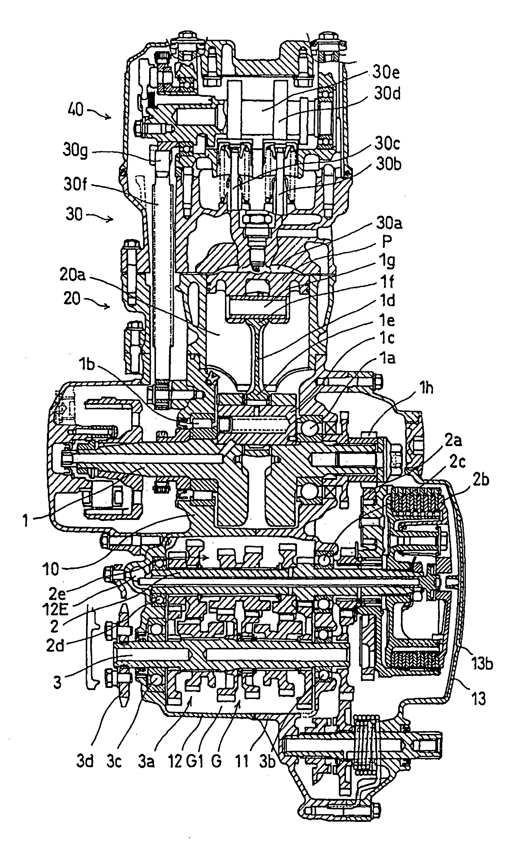
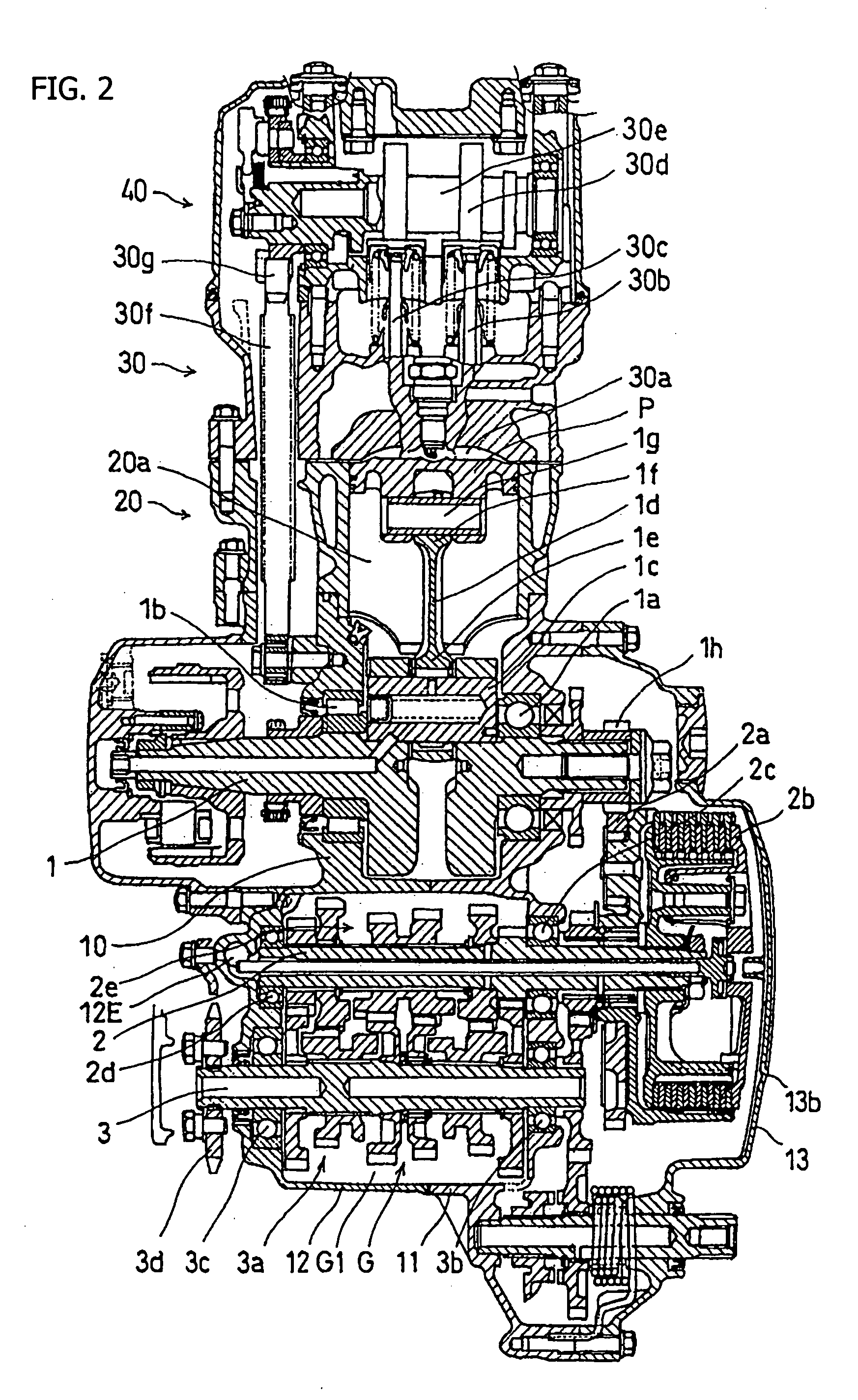
[0015] In a first aspect of the present invention, a lubrication structure in an engine includes an oil receiver. The oil receiver has an oil guide plate for guiding oil, which has been scooped up by the rotary member, to the oil receiver. Accordingly, it is possible to effectively guide oil, which has spattered in multiple directions, to the oil receiver via the oil guide plate and thereby improve oil recovery efficiency. As a result, it is made possible to improve lubrication performance in an engine.
[0016] In a second aspect of the present invention, the oil guide plate described above is capable of guiding the scooped oil to the oil receiver since the oil guide plate abuts the oil receiver, and the oil receiver is positioned above the gear engagement part of the transmission system. Accordingly, it is possible to effectively guide oil, which has spattered in multiple directions, to the oil receiver via the oil guide plate and to improve oil recovery efficiency. In addition, since the oil receiver is positioned above the gear engagement portion, received oil drops by gravity down upon the gear engagement portion. The gear engagement portion is thereby lubricated effectively. As a result, it is possible to improve lubrication performance in an engine.
[0017] In a third aspect of the present invention, an upper portion of the oil guide plate described above has a bent upper edge part for guiding the scooped oil to the oil receiver. The bent upper edge part is inclined, and the upper edge thereof is bent in a direction away from the oil receiver. Accordingly, the scooped oil is smoothly guided by the bent upper edge part, so as to highly effectively guide the oil to the oil receiver.
[0018] In a fourth aspect of the present invention, a roof plate covers the guide plate when viewed from the side, and is arranged to cooperate with the guide plate. The roof plate has a structure for capturing oil which has been scooped up by the rotary member and for guiding the captured oil to the oil receiver described above. Accordingly, the oil which has been scooped up by the rotary member, and has been captured by the roof plate, is efficiently guided to the oil receiver via the oil guide plate and is recovered.
[0019] In a fifth aspect of the present invention, the roof plate described above is inclined in a way that oil is guided to the oil receiver by flowing along the surface thereof. Accordingly, the oil which has been scooped up by the rotary member moves along the surface of the roof plate and thereby the oil is efficiently guided to the oil receiver.

Problems solved by technology

Accordingly, selection of a structure or shape which has a sufficient oil recovery function as an oil receiver is restricted.

Method used


Image

  • Lubrication system and method, and engine incorporating same
  • Lubrication system and method, and engine incorporating same
  • Lubrication system and method, and engine incorporating same

Examples


Embodiment Construction

[0034] A selected illustrative embodiment of the present invention will be now described, with respect to the drawing figures.

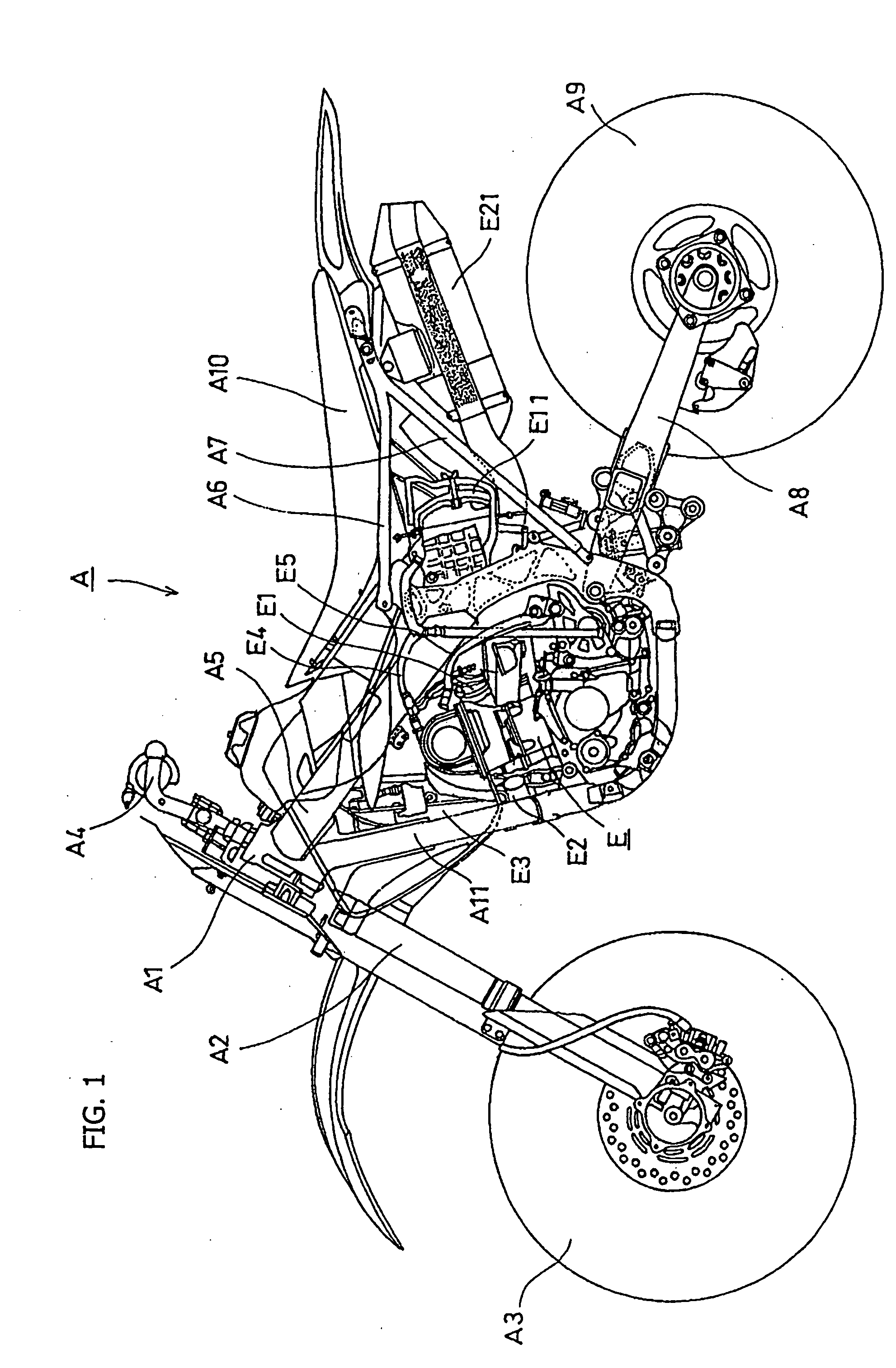
[0035]FIG. 1 is a side plan view of a motorcycle which is a vehicle A provided with an engine E. The engine E is provided with an improved lubrication structure according to an embodiment of+ the present invention. The motorcycle of the present invention includes a head pipe A1 as a frame member for the front thereof. A front fork A2 is attached below the head pipe A1. A front wheel A3 is rotatably supported by the front fork A2. Above the head pipe A1, a handle bar A4 is attached.

[0036] In addition, a mainframe A5 is connected to the head pipe A1, obliquely pointing downward and extending in a rear direction therefrom. A seat rail A6 is attached to the rear upper portion of the mainframe A5. The a seat rail A6 extends in a rear direction and points in a substantially horizontal direction therefrom. Moreover, a rear end portion of the mainframe A5 bends dow...


PUM


Abstract

An improved lubrication structure is provided in a engine by optimizing the structure for recovering scooped oil for enhanced oil recovery efficiency. The oil, which has been scooped up and scattered by the rotation of a clutch, is captured within a concave groove provided within a cylindrical inner surface of a case cover facing the clutch. The captured oil is smoothly guided from the concave groove to an oil receiver of a crankcase via a bent upper edge part of an oil guide plate. The recovered oil passes through dropping holes of a recovered oil path and is supplied to a gear engagement part of a transmission system located below the recovered oil path.

Description

CROSS-REFERENCE TO RELATED APPLICATIONS [0001] The present invention claims priority under 35 USC 119 based on Japanese patent application No. 2004-066241, filed on Mar. 9, 2004. The subject matter of this priority document is incorporated by reference herein. BACKGROUND OF THE INVENTION [0002] 1. Field of the Invention [0003] The present invention relates to a lubrication system and method for a powertrain assembly, and more particularly relates to improved technology for a lubrication system in which lubrication is performed by mechanically scooping up oil accumulated in the lower part of a crankcase, and distributing the scooped-up oil to internal components of the powertrain. [0004] 2. Background of the Invention [0005] In Japanese Utility Model Publication No. Hei 05-33686, a known lubrication structure is described, for an engine having a clutch mounted on a main transmission drive shaft that rotates in conjunction with a crankshaft. In the known structure, oil accumulated in ...

Claims


Application Information

Patent Timeline
IPC IPC(8): F01M1/00F01M1/06F01M9/06F01M9/08F01M9/10F16N7/18
CPCF16H57/0421
Inventor HAMADA, YASUNOBUTAKAHASHI, ISAMU
Owner HONDA MOTOR CO LTD
Learn More