
Floor type multi-rope oil extractor system

A pumping unit and floor-standing technology, which is applied to the automatic control system of drilling, production fluid, drilling equipment, etc., can solve the problems of no closed-loop feedback mechanism, lack of applicability, flexibility and robustness, etc., to avoid high-speed production Low fluid volume or idling, convenient and simple parameter adjustment, and the effect of improving downhole efficiency

Active Publication Date: 2019-12-20
胜利方兰德石油装备股份有限公司
View PDF8 Cites 6 Cited by
  • Summary
  • Abstract
  • Description
  • Claims
  • Application Information

AI Technical Summary

Problems solved by technology

Frequency conversion speed regulation has many advantages such as wide speed regulation range, high system efficiency, high control precision, easy automation and intelligent control, etc. However, the current frequency conversion speed regulation technology directly controls the motor by directly setting the frequency. No closed-loop feedback mechanism, lack of applicability, flexibility, and robustness

Method used


Image

  • Floor type multi-rope oil extractor system
  • Floor type multi-rope oil extractor system
  • Floor type multi-rope oil extractor system

Examples


Embodiment Construction

[0052] In order to make the purpose, technical solution and advantages of the present invention clearer, the technical solution of the present invention will be described in detail below. Apparently, the described embodiments are only some of the embodiments of the present invention, but not all of them. Based on the embodiments of the present invention, all other implementations obtained by persons of ordinary skill in the art without making creative efforts fall within the protection scope of the present invention.

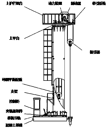
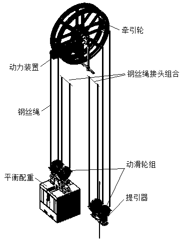
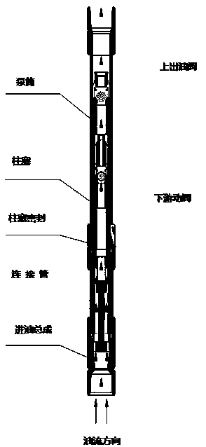
[0053] see Figure 1-Figure 3 As shown, a floor-standing multi-rope pumping unit system includes a main body of the pumping unit, a gas injection thermal recovery pump and a packer assembly. The main body of the pumping unit is connected to the gas injection thermal recovery pump through its traction system. The gas injection thermal recovery oil well pump is connected to the packer assembly through a hands-off joint,

[0054] The main body of the pumping unit...


PUM


Abstract

The invention discloses a floor type multi-rope oil extractor system. The system comprises an oil extractor main body, a gas injection thermal recovery oil extracting pump and a packer module; the oilextractor main body is connected with the gas injection thermal recovery oil extracting pump through a traction system thereof; the gas injection thermal recovery oil extracting pump is connected with the packer module through a hand-free joint; the oil extractor main body comprises a concrete foundation, a shifter guide rail, a rail clamper module, a control cabinet, a bracket, an adjustable balance counterweight, an upper platform, an upper guard combination, a power device, a brake, the traction system and an elevator; the traction system comprises a traction wheel, a steel wire rope, a movable pulley set and a steel wire rope joint; the steel rope is divided into an elevation steel wire rope and a balance steel wire rope; one end of the elevation steel wire rope is fixed on the traction wheel and bypassed through the traction wheel, and the other end is fixedly connected with the steel wire rope joint on the bracket through the elevator and the movable pulley on the elevator; andthe balance steel wire rope is opposite to the elevation steel wire rope, one end is fixed on the traction wheel and bypassed through the traction wheel, and the other end is fixedly connected with the steel wire rope joint on the bracket through the adjustable balance counterweight and the movable pulley on the adjustable balance counterweight.

Description

technical field [0001] The invention relates to the technical field of pumping units, in particular to a floor-standing multi-rope pumping unit system. Background technique [0002] In recent years, as the world's energy problems have become increasingly prominent, energy conservation of pumping units has become a major concern of people. Various domestic manufacturers and research institutes continue to apply new technologies, through structural optimization design and improved balance methods, etc., to achieve pumping units. The purpose of energy saving of oil pumps is to reduce energy consumption and reduce oil production costs. A batch of new pumping units have been put into oil field production in the past few years. How to ensure high pumping efficiency, long life of pumping units, small dynamic load, and Quantity stability is also a problem that pumping units are currently facing. [0003] In addition, in the process of heavy oil production, due to high viscosity and...

Claims


Application Information

Patent Timeline
Patent Type & Authority Applications(China)
IPC IPC(8): E21B43/00E21B19/084E21B17/10E21B43/24E21B44/00E21B47/00
CPCE21B17/1078E21B19/084E21B43/121E21B43/24E21B44/00E21B47/00
Inventor 赵玉刚付少彬董洪芳
Owner 胜利方兰德石油装备股份有限公司
Learn More