
Heat spreader for rotary rheometer

a rotary rheometer and heat spreader technology, applied in the field of rheometers, can solve the problems of increasing error, affecting the accuracy and validity of measurement, and controlling the temperature from just one side of the sample in this manner, so as to reduce the chimney effect, reduce the inertia, and maximize the surface area

Active Publication Date: 2005-09-15
WATERS TECH CORP
View PDF7 Cites 13 Cited by
  • Summary
  • Abstract
  • Description
  • Claims
  • Application Information

AI Technical Summary

Benefits of technology

The present invention is a rotary rheometer that has an upper assembly with active heating elements to heat the sample from more than just the bottom plate. The design of the rheometer includes an efficient method of transferring heat and cold by placing heating elements in communication with a heat spreader to transfer the heat to the upper geometry. The upper heating assembly includes a pair of interlocked or mated elements that can be calibrated and employed to actively heat the sample gap from the above in addition to the lower heating plate. The design is insensitive to changes in geometry gap or diameter, so calibration and re-calibration is kept to a minimum. The temperature of the upper plate may further be modeled and the lower plate matched to it, meaning that the two plates remain closely coupled during temperature ramps, thus meaning that the temperature displayed by the rheometer is that of both plates, not just the lower one.

Problems solved by technology

If the temperature of the material being tested were not homogeneous, the accuracy and validity of the measurement would be seriously compromised.
Controlling the temperature from just one side of the sample in this manner can introduce error.
As testing moves further away from ambient temperatures, error may increase due to the likelihood of increased temperature gradients.
Increasing geometry gap as well as increasing temperature sensitivity of the sample may also increase error.
For many applications, especially those occurring near ambient temperature, the error associated with single-side heating is insignificant.
Peltier plates may not, however, be the most desirable manner of heating the upper geometry of a rheometer.
Such a flow of air can lead to undesirable cooling or simply affect heating of the sample such that the measurements taken become less accurate.

Method used


Image

  • Heat spreader for rotary rheometer
  • Heat spreader for rotary rheometer
  • Heat spreader for rotary rheometer

Examples


Embodiment Construction

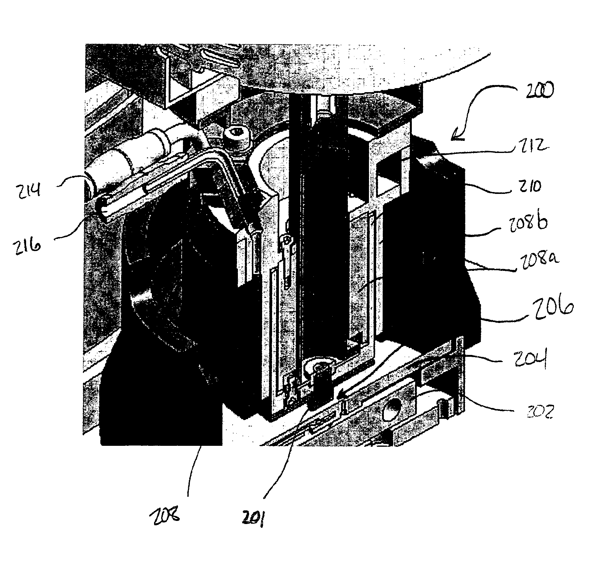
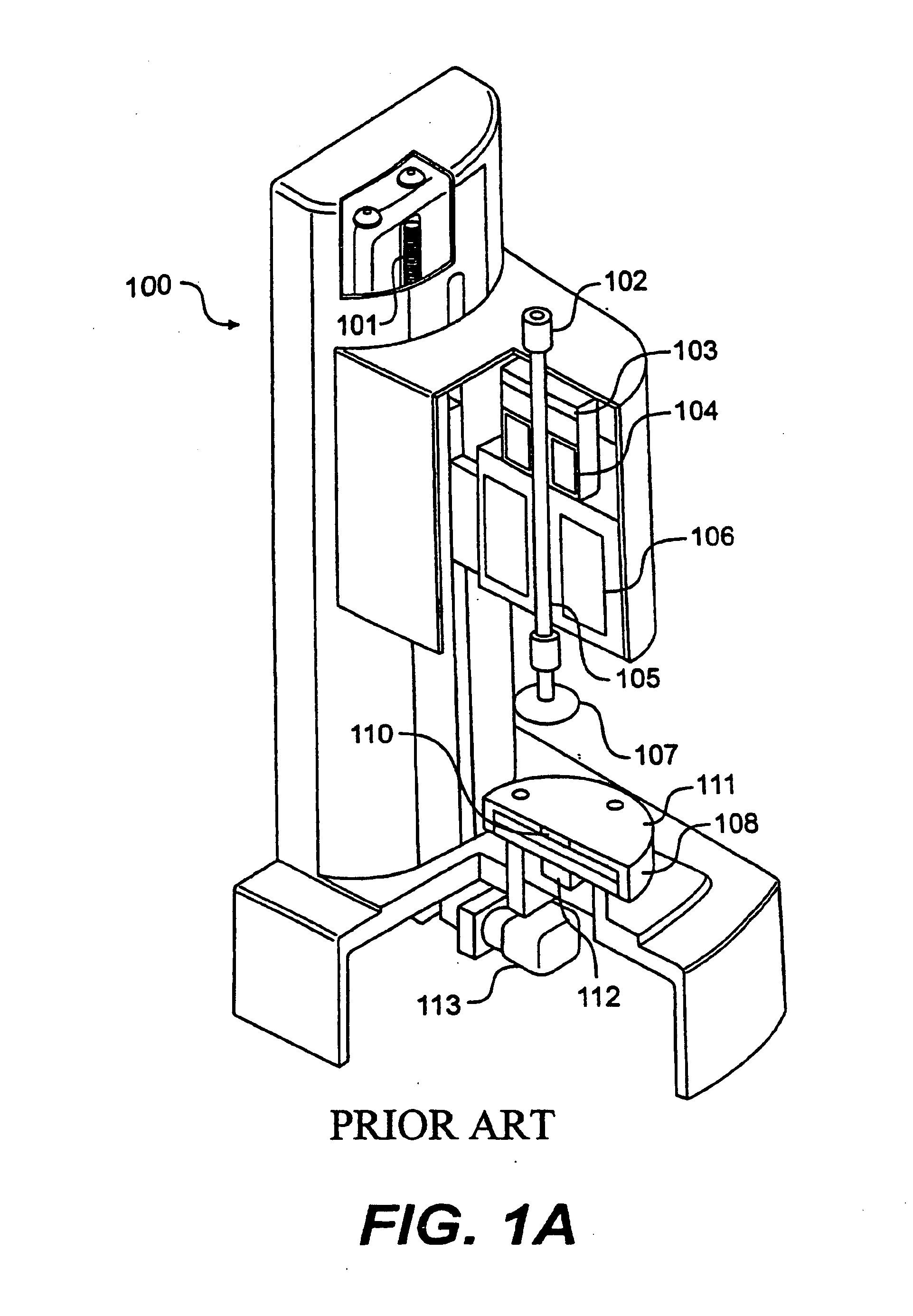
[0018]FIG. 2 is a perspective cut-away schematic diagram that shows an exemplary embodiment of the upper geometry heater of the present invention. As shown, rheometer 200 is similar in most functional rehometry aspects as prior art devices. It includes upper geometry 201, a Peltier plate heater 202, a lower heat spreader 204 for distributing the heat generated by heater 202 to sample gap 206, which is located between the upper geometry 201 of rheometer 200 and lower heat spreader 204. Above sample gap 206, however, is an upper heat plate assembly 208 comprising an inner portion 208a and an outer portion 208b. Inner portion 208a and outer portion 208b combine to form an inverted “U” shaped heating element. One of skill in the art will understand the inner portions 208a and 208b may comprise a single unitary element or may comprise separate elements that may or may not be connected to one another. Upper heat plate assembly 208 fits over upper geometry heat spreader 210, which takes th...


PUM

PropertyMeasurementUnit
viscosityaaaaaaaaaa
elasticityaaaaaaaaaa
yield stressaaaaaaaaaa

Abstract

A rotary rheometer having a an upper heating / cooling assembly and a lower heating / cooling assembly located opposite one another opposite a sample gap. The lower heating / cooling assembly may comprise a Peltier heater and the upper heating / cooling assembly preferably comprises a heating element that mates with a heat spreader for heating and cooling the area above the sample and providing more uniform heating and cooling across the sample gap while also minimizing any chimney effect within the rheometer and / or providing heating / cooling capability that is insensitive to changes in the gap between an upper geometry and the lower heating / cooling assembly. The upper heating / cooling assembly may further comprise a cooling channel for cooling the upper heating / cooling assembly.

Description

[0001] This application claims the benefit of U.S. Provisional Application No. 60 / 551,331, filed Mar. 10, 2004, which is herein incorporated by reference in its entirety.BACKGROUND [0002] 1. Field of the Invention [0003] The present invention relates generally to rheometers, which are used to characterize materials by measuring the materials' viscosity, elasticity, shear thinning, yield stress, compliance and / or other material properties. [0004] 2. Background of the Invention [0005] Rotary rheometers, viscometers or viscosimeters are used to measure fluid or other properties of materials such as their viscosity by rotating, deflecting or oscillating a measuring object in a material, and measuring, for example, the torque required to rotate or deflect or oscillate the object within the material. As used herein, the term “rheometer” shall mean rheometers, viscometers, viscosimeters and similar instruments that are used to measure the properties of fluid or similar (see list below) mat...

Claims


Application Information

Patent Timeline
Patent Type & Authority Applications(United States)
IPC IPC(8): G01N11/00
CPCG01N2011/002G01N11/14
Inventor DOE, NIGELFOSTER, PETER
Owner WATERS TECH CORP
Learn More