
Variable steerable catheters and methods for using them

Inactive Publication Date: 2005-09-08
INTUITIVE SURGICAL OPERATIONS INC
View PDF57 Cites 326 Cited by
  • Summary
  • Abstract
  • Description
  • Claims
  • Application Information

AI Technical Summary

Benefits of technology

[0011] In accordance with another embodiment, a method is provided for delivering one or more therapeutic and / or diagnostic agents into tissue. A distal end of a tubular member may be advanced into a body lumen, and an expandable member on the distal end of the tubular member may be expanded within the body lumen. The expanded expandable member may be directed against a wall of the body lumen, allowing direct visualization or other imaging through the expandable member to observe tissue beyond the expandable member. The tubular member may be manipulated to move the expandable member relative to the wall to identify a desired tissue structure, and one or more agents may be injected from the tubular member into the desired tissue structure once it is identified. In an exemplary embodiment, the desired tissue structure may include infarcted tissue and the agent(s) may include stem cells to enhance regeneration of the infarcted tissue.
[0016] In accordance with yet another embodiment, a method is provided for accessing a body lumen within a patient's body. A distal end of a tubular member may be advanced into a body lumen. An axial force may be applied to a steering element extending from a proximal end of the tubular member to a distal portion of the tubular member to cause the distal portion to curve or bend, and a portion of the steering element may be directed within the distal portion from a first region aligned within a center of modulus of the distal portion to a second region within the distal portion, thereby adjusting a radius of curvature of the distal portion.

Problems solved by technology

However, such stiffening members may also change the stiffness of all or portions of the catheter, which may be undesirable, e.g., when passing the catheter through tortuous anatomy.

Method used


Image

  • Variable steerable catheters and methods for using them
  • Variable steerable catheters and methods for using them
  • Variable steerable catheters and methods for using them

Examples


Embodiment Construction

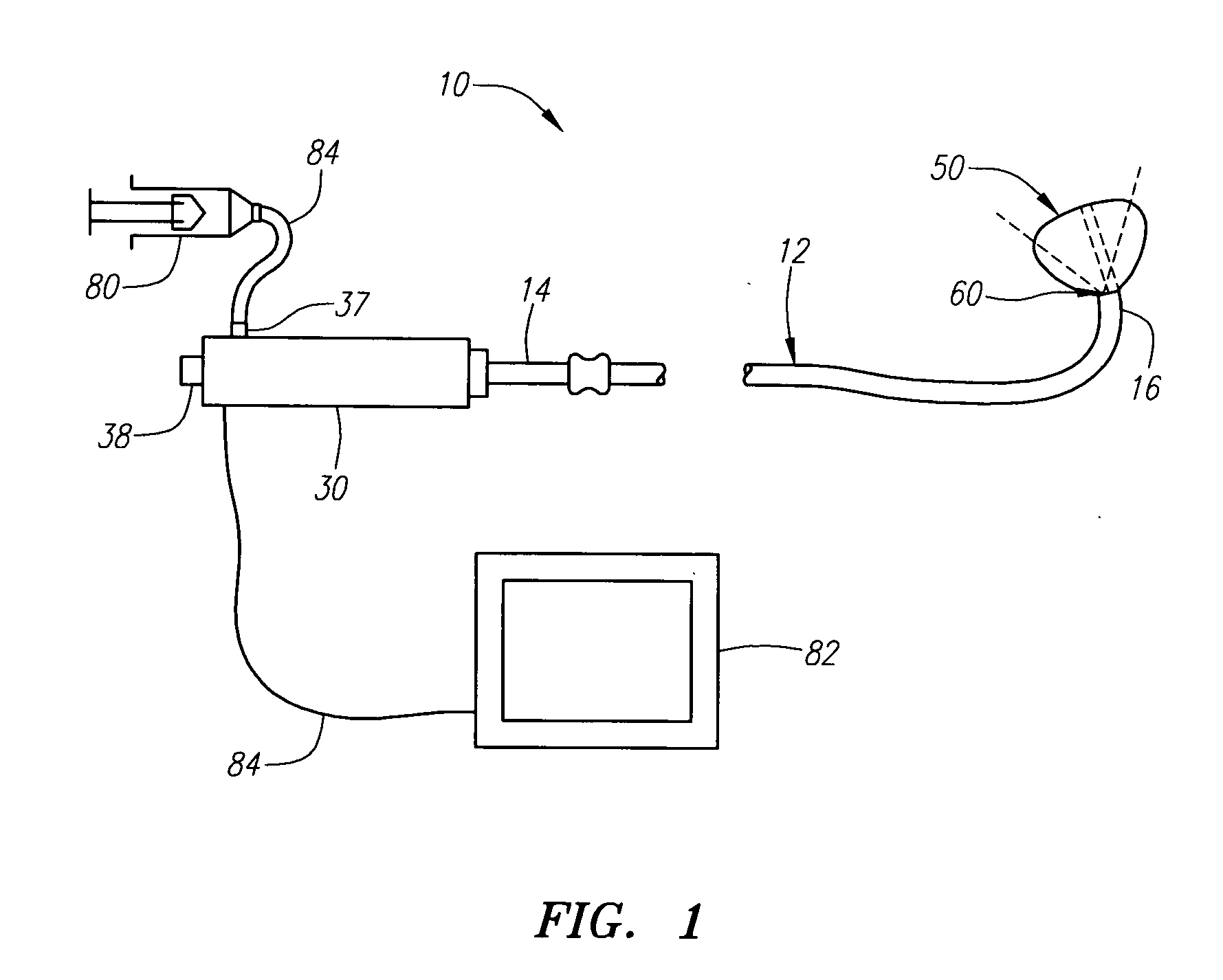
[0078] Turning to the drawings, FIG. 1 shows a first embodiment of an apparatus 10 for imaging a body lumen, e.g., for visualizing, accessing, and / or cannulating a body lumen from a body cavity (not shown). As explained further below, the apparatus 10 may be used for imaging a wall of a body lumen, e.g., a right atrium of a heart, e.g., for visualizing, accessing, and / or cannulating a coronary sinus ostium. Alternatively, the apparatus 10 may be used for visualizing, accessing, and / or cannulating other body lumens, e.g., for delivering one or more therapeutic and / or diagnostic agents into tissue, and / or for puncturing through tissue to access a region beyond the punctured tissue. As used herein, “body lumen” may refer to any passage within a patient's body, e.g., an artery, vein, or other blood vessel, or a body cavity, such as a chamber within a patient's heart, e.g., a ventricle or atrium. Although exemplary embodiments are described herein, additional information that may relate ...


PUM


Abstract

An apparatus for accessing a body lumen includes a tubular member including a proximal end, a distal end sized for introduction into a body lumen, and a passage extending along a steerable distal portion of the tubular member. The passage includes a first region extending substantially parallel to a center of modulus of the distal portion and a second region offset from the center of modulus. A steering element is disposed through the passage extending along the distal portion that includes a proximal end disposed adjacent the tubular member proximal end, and a distal end fixed to the tubular member distal end beyond the distal portion. A steering adjustment member is slidable within the passage for selectively directing a portion of the steering element between the first and second regions to vary the steerability of the distal portion.

Description

[0001] This application is a continuation-in-part of co-pending application Ser. No. 11 / ______, filed Feb. 11, 2005, entitled “Steerable Catheters and Methods for Using Them” (attorney matter no. ACU-011), and claims benefit of provisional application Ser. Nos. 60 / 545,865, filed Feb. 17, 2004, and 60 / 549,343 and 60 / 549,344, filed Mar. 1, 2004. The entire disclosures of these applications are expressly incorporated herein by reference.FIELD OF THE INVENTION [0002] The present invention relates generally to catheters for introduction into body lumens within a patient's body, and, more particularly, to steerable catheters for visualization within a patient's body and / or for accessing body lumens, and to methods for using such catheters. BACKGROUND [0003] Minimally invasive procedures have been implemented in a variety of medical settings, e.g., for vascular interventions, such as angioplasty, stenting, embolic protection, electrical heart stimulation, heart mapping and visualization, t...

Claims


Application Information

Patent Timeline
IPC IPC(8): A61M29/00A61M31/00A61M37/00
CPCA61M25/0136A61M25/0144A61M25/104A61M2025/0024A61B1/018A61B1/00078A61B1/00082A61B1/0055A61M2025/0681
Inventor LEEFLANG, STEPHEN A.LOFTHOUSE, TREVOR A.MORRISON, GEORGEMOURLAS, NICHOLAS J.EVERSULL, CHRISTIAN S.
Owner INTUITIVE SURGICAL OPERATIONS INC
Learn More