Signal-transmitting system, data-transmitting apparatus and data-receiving apparatus

a technology which is applied in the field of signal transmission system and data transmission apparatus, can solve the problems of unnatural cursor movement of cursor in image, imposing limitations on representation, and thick cable, and achieves stable transmission of image data and shortening the time elapsed

Inactive Publication Date: 2005-09-08
SONY CORP
View PDF8 Cites 3 Cited by
  • Summary
  • Abstract
  • Description
  • Claims
  • Application Information

AI Technical Summary

Benefits of technology

[0019] The signal-transmitting system according to this invention can shorten the time that elapses until an image is displayed after a request for updating the image displayed is made. In addition, the system can realize a stable transmission of image data in data communication at a fixed transmission rate. The system is useful, particularly in transmitting high-precision image signals of XGA format or any hither mode.

Problems solved by technology

Due to the band allocated to the signals, the cable is thick and short.
This inevitably restricts the position of the computer and that of the projector, ultimately imposing limitations on the representation.
Here arises the problem that the cursor in the image moves unnaturally when a presenter moves a mouse.
They are not fit for encoding computer outputs (particularly, high-precision text images).
As a consequence, the image-transmitting system will be a large-scale and high-cost system.
This system can preserve the quality of the original images, but is disadvantageous in the following respect.
Consequently, the cost of the system will increase.
Additionally, the LAN connection cannot be utilized only if a VGA cable connects the computer and the display.
The method of setting the system is inevitably complicated.
However, a greater part of the original image data input may change, or the data of an image to be displayed may greatly change as in the case of a page change.
In either case, the amount of data to be transmitted increases, inevitably causing a time lag between the start of image-data transmission and the displaying of the image.
As a consequence, the image cannot be displayed at the very time it is explained in a presentation.
This makes it impossible to perform smooth presentations.

Method used


Image

  • Signal-transmitting system, data-transmitting apparatus and data-receiving apparatus
  • Signal-transmitting system, data-transmitting apparatus and data-receiving apparatus
  • Signal-transmitting system, data-transmitting apparatus and data-receiving apparatus

Examples


Embodiment Construction

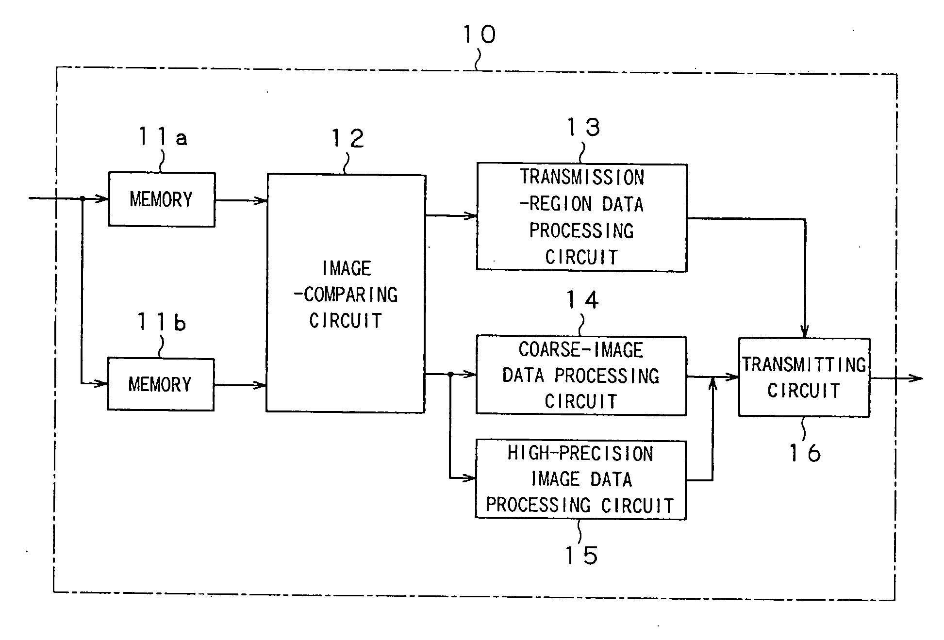
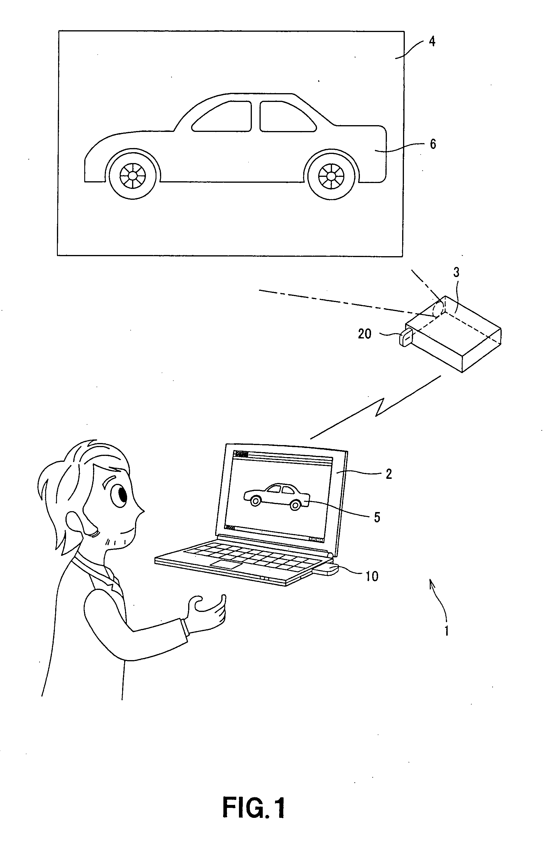
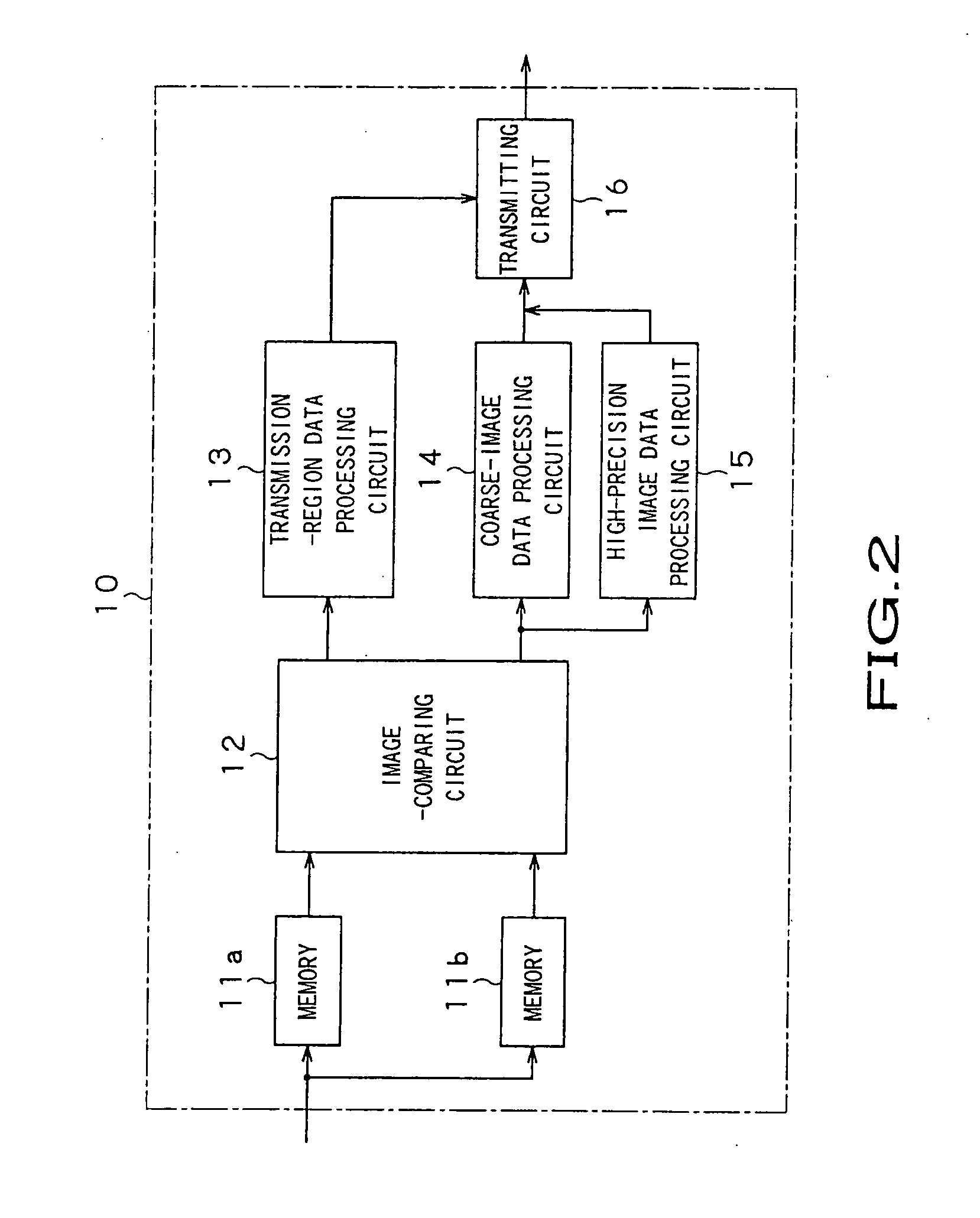
[0026] A signal-transmitting system, which is an embodiment of the present invention, is a system that comprises a data-processing terminal such as a personal computer (PC) and a peripheral apparatus connected to the terminal. In the system, the peripheral apparatus is an image-projecting apparatus (hereinafter referred to as “projector”). The projector is connected to the PC by a network. The image data that represents an image displayed on the monitor of the PC is transmitted to the projector. The projector can therefore project the image on a screen. The image data handled in this embodiment represents a still picture displayed on the computer screen. The still picture may be, mainly, a diagram or an image containing text data, which can be prepared and processed by using PC software. The still picture is an image more abstract than a picture that is represented by image data generated from a part of a photograph or a video picture.

[0027] In this system comprising the PC and the...


PUM


Abstract

In the data-transmitting apparatus, the image-comparing circuit compares, when a request for updating the image displayed is made, the image data item being input, with the image data item stored in the memories, which represents the preceding frame. The circuit therefore calculates the difference between the image data items compared. If the difference thus calculated by the image-comparing circuit is smaller than a prescribed value (if No in Step S1), the transmission-region data processing circuit generates, from the difference of the image data, the data that represents that part of the image data which corresponds to a region to be transmitted, and the data that represents this region. These data items generated by the circuit are transmitted. If the difference thus calculated is equal to or greater than the prescribed value (if Yes in Step S1), the coarse-image data processing circuit generates coarse image data, which is transmitted. Next, the high-precision image data processing circuit transmits full-size image data (Step S4).

Description

BACKGROUND OF THE INVENTION [0001] 1. Field of the Invention [0002] The present invention relates to a data-transmitting apparatus that transmits, for example, still-picture signals to a large-image display apparatus such as a projector or a PDP. The invention also relates to a data-receiving apparatus that receives signals transmitted and a data-transmitting system that uses the data-transmitting apparatus and the data-receiving apparatus. [0003] This application claims priority of Japanese Patent Application No. 2004-061467, filed on Mar. 4, 2004, the entirety of which is incorporated by reference herein. [0004] 2. Description of the Related Art [0005] Image data processed in computers at present has high precision. To cope with this, the image resolution achieved by display elements has increased. In view of this technical trend, the technique of inputting image signals from computers to a liquid crystal projector and projecting the images represented by the signals, thereby to p...

Claims


Application Information

Patent Timeline
Patent Type & Authority Applications(United States)
IPC IPC(8): G06F3/14G06K9/36H04N19/50G06K9/46G09G5/00H04N11/06H04N11/24H04N19/102H04N19/134H04N19/136H04N19/196H04N19/423
CPCG06F3/1407H04N19/132H04N19/36H04N19/184H04N19/507H04N19/137
Inventor KAIDA, SHUNSUKE
Owner SONY CORP
Why Eureka
Try Eureka