Grasping device

a technology of grasping device and forming machine, which is applied in the direction of lighting and heating apparatus, charge manipulation, furnaces, etc., can solve the problems of lowering the efficiency of molding by injection molding machine and the efficiency of forming by in-mold molding machine, and achieve the effect of shortening the time to elaps

Active Publication Date: 2010-06-22
YUSHIN PRECISION EQUIP
View PDF14 Cites 0 Cited by
  • Summary
  • Abstract
  • Description
  • Claims
  • Application Information

AI Technical Summary

Benefits of technology

[0021]An object of the present invention is to provide a grasping device wherein vibration of the grasping device due to inertia arising upon stoppage after being moved is restrained to shorten time to elapse until disappearance of the vibration, whereby contributing to improvement of production efficiency of a production facility.
[0023]According to the grasping device of the first invention structured as above, since the grasping part is structured with the group of branches having a plurality of branches diverged and extended from the base, the grasping part's utmost end side most away from the base is small in weight (i.e., to be light). Thus, vibration of the grasping device due to inertia arising upon stoppage of the grasping device after being moved is restrained to shorten time to elapse until disappearance of the vibration, whereby contributing to improvement of production efficiency of a production facility.
[0025]According to the grasping device, since the grasping part's utmost end side most away from the base is further smaller in weight (i.e., to be lighter), vibration of the grasping device due to inertia arising upon stoppage of the grasping device after being moved is further restrained to thereby more shorten the time to elapse until disappearance of the vibration.
[0027]According to the grasping device also, since the grasping part's utmost end side most away from the base is small in weight (i.e., to be light), vibration of the grasping device due to inertia arising upon stoppage of the grasping device after being moved is restrained to shorten time to elapse until disappearance of the vibration.

Problems solved by technology

As a result, a cycle time of grasping the molded articles by the grasping device 50 is inevitably longer, which causes lowering of an efficiency of molding by the injection molding machine.
As a result, a cycle time of inserting the work by the grasping device 60 is inevitably longer, which causes lowering of an efficiency of forming by an in-mold forming machine.

Method used


Image

  • Grasping device
  • Grasping device
  • Grasping device

Examples


Embodiment Construction

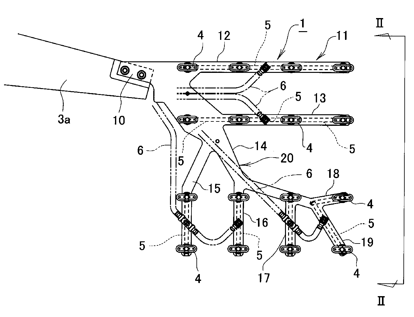
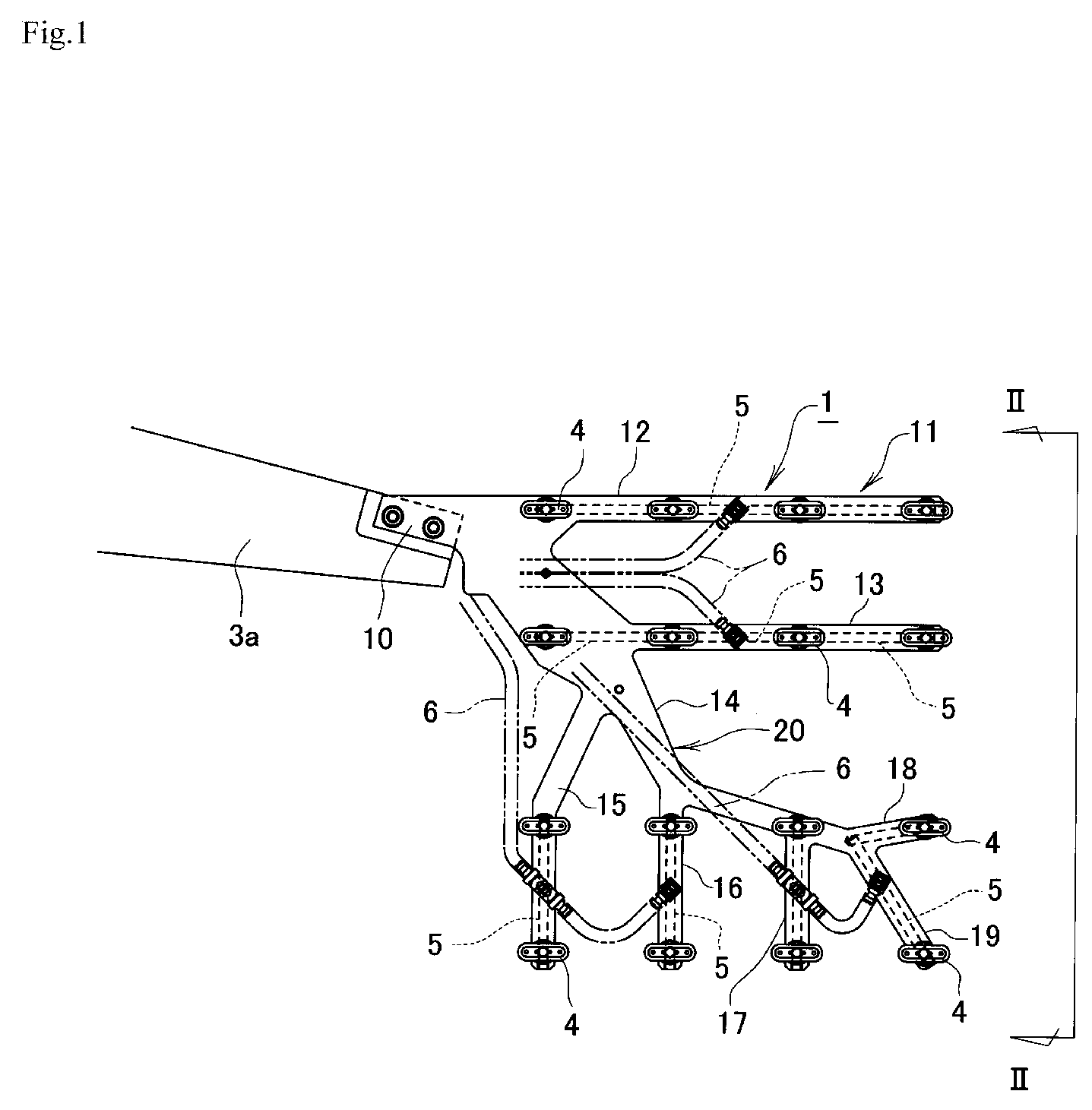
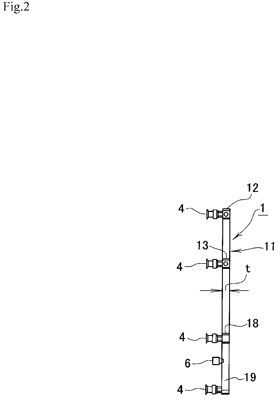
[0041]FIG. 1 is a front view showing a grasping device according to the first invention of the present invention in a first Example. FIG. 2 is a side view taken from the arrowed line II-II in FIG. 1. And FIG. 3 is a front view showing an example of use of the grasping device shown in FIG. 1.

[0042]In FIGS. 1, 2, and 3, a grasping device 1 is provided for grasping and taking out at a time sixteen (16) small molded articles (“work(s)” (not shown)) molded (produced) simultaneously by an injection molding machine (a production facility) 2. The grasping device 1 is mounted to an utmost end of a rotating arm 3a of a molded article take-out machine (a conveying means) 3 which conveys the sixteen small molded articles from a “work grasping position” (see the solid line in FIG. 3) facing an opened mold 2a in an injection molding machine 2 to a “work-release position” (two-dots chain line in FIG. 3) outside the injection molding machine 2.

[0043]The grasping device 1 is made of a metal plate or...


PUM

PropertyMeasurementUnit
specific cross sectional areasaaaaaaaaaa
timeaaaaaaaaaa
thicknessaaaaaaaaaa

Abstract

A grasping device can be provided on a conveyor which conveys works produced by a production facility or a work subjected to in-mold forming from a work-grasping position to a work-releasing position. The example of a grasping device can include a base at the side of the conveyors and a grasping part which is extended from the base and provided with a plurality of grasping heads. The example of a grasping part can include a group of branches having a plurality of diverged and extended branches, specific branches most apart from the base each being small in weight (being light) at utmost end side.

Description

BACKGROUND OF THE INVENTION[0001]1. Field of the Invention[0002]The present invention relates to a grasping device, particularly, to a grasping device suitable for such grasping devices as that usable for grasping and taking out at a time many small molded articles or works which molded at a time by an injection molding machine, or that usable, in insert-molding technique integrally molding a thin work and synthetic resin, for grasping the thin work and inserting it into a mold in an injection molding machine.[0003]2. Description of the Prior Art[0004]Conventionally, in a synthetic resin molding technology, particularly, in a system of taking out molded works which system is called “a lot of articles take-out system” and grasps and takes out at a time many small molded articles molded at a time, a grasping device 50 shown in FIGS. 9, 10 and 11 is employed.[0005]In FIGS. 9, 10 and 11, the grasping device 50 is provided for grasping and taking out at a time many small molded articles ...

Claims


Application Information

Patent Timeline
Patent Type & Authority Patents(United States)
IPC IPC(8): B65G47/34
CPCB25J15/0052B65G47/918B65G47/91B25J15/0616
Inventor KITA, MEGUMISUZUTANI, HIDEKI
Owner YUSHIN PRECISION EQUIP
Why Eureka
Try Eureka