
Method of detecting video shot changes in a moving picture and apparatus using the same

a technology of moving picture and video, applied in the field of video shot change detection in moving picture data, can solve the problems of large computational load of conventional shot change detection schemes, inability to improve processing speed, and inefficiency of such detection schemes

Inactive Publication Date: 2005-09-08
SAMSUNG ELECTRONICS CO LTD
View PDF0 Cites 6 Cited by
  • Summary
  • Abstract
  • Description
  • Claims
  • Application Information

AI Technical Summary

Problems solved by technology

However, conventional shot change detection techniques on the compressed or the non-compressed domain generally have the following limitation.
Accordingly, the computational load of such detection schemes is very large and inefficient, thereby not permitting the improvement of the processing speed.
Secondly, a conventional approach employing a color histogram difference as a main detection measure reveals the limitation on the shot change detection between temporally neighboring video shots with similar color distributions.
Besides, in news video or music videos where a type of significant illumination change such as a flashlight frequently is observed, a number of false shot changes are detected around the video frames with flashlight.

Method used


Image

  • Method of detecting video shot changes in a moving picture and apparatus using the same
  • Method of detecting video shot changes in a moving picture and apparatus using the same
  • Method of detecting video shot changes in a moving picture and apparatus using the same

Examples


Embodiment Construction

[0039] Reference will now be made in detail to the embodiments of the present invention, examples of which are illustrated in the accompanying drawings, wherein like reference numerals refer to the like elements throughout. The embodiments are described below to explain the present invention by referring to the figures.

[0040] The present invention will now be described more fully with reference to the accompanying drawings, in which exemplary embodiments of the invention are shown. The invention may, however, be embodied in many different forms and should not be construed as being limited to the embodiments set forth herein; rather, these embodiments are provided so that this disclosure will be thorough and complete, and will fully convey the concept of the invention to those skilled in the art. Like reference numerals in the drawings denote like elements, and thus their description will be omitted.

[0041] Referring to FIG. 1, a method of detecting video shot changes in a moving pi...


PUM

PropertyMeasurementUnit
color histogramaaaaaaaaaa
thresholdaaaaaaaaaa
threshold valueaaaaaaaaaa

Abstract

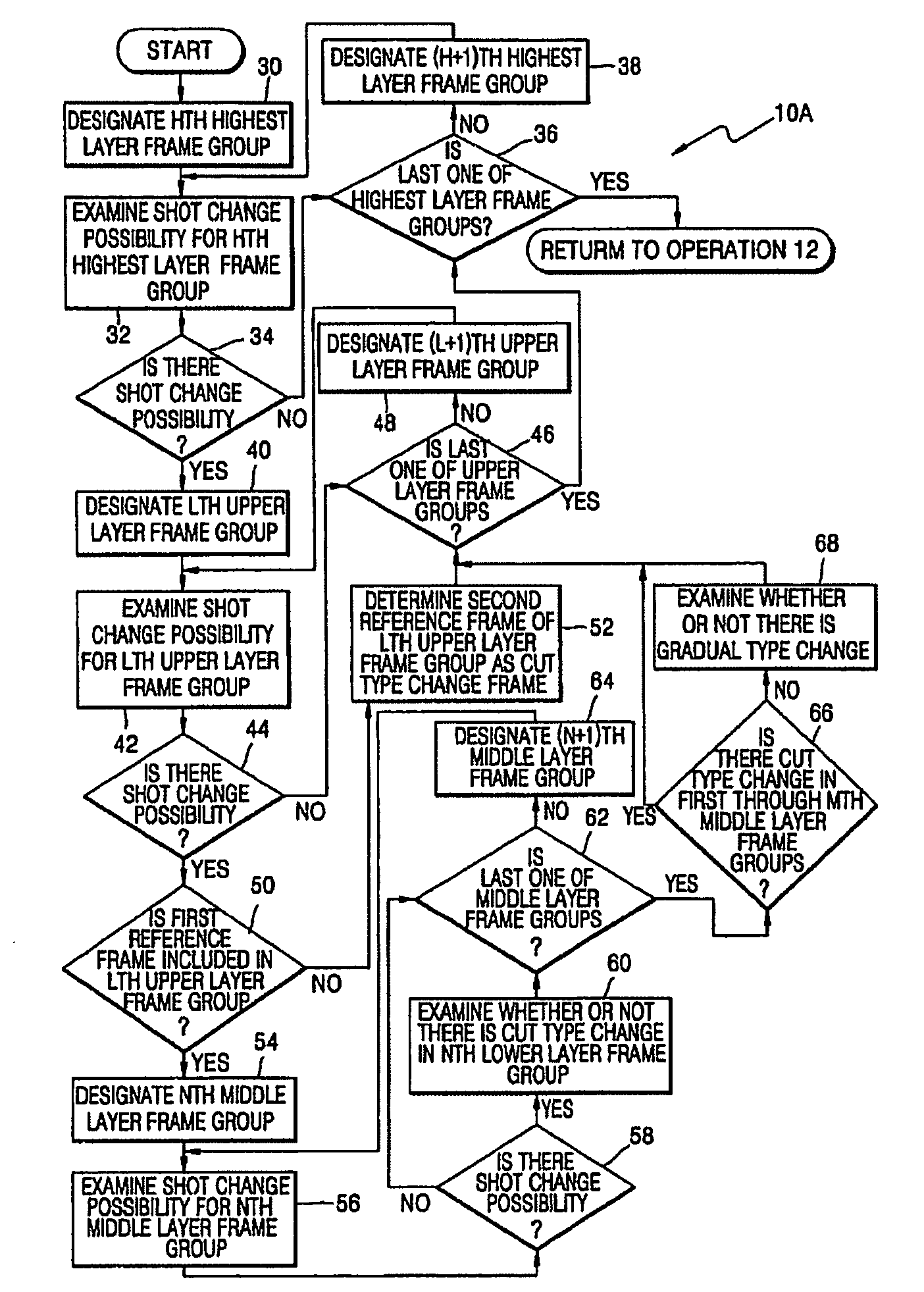
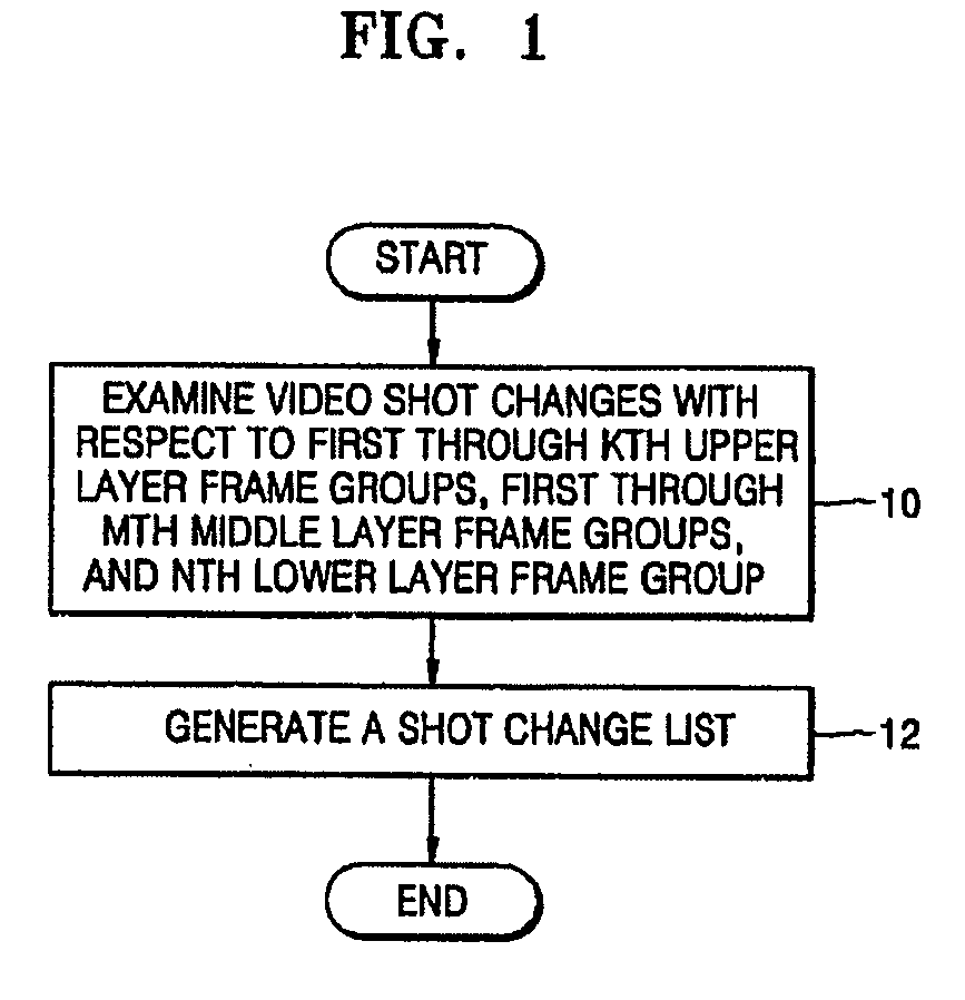
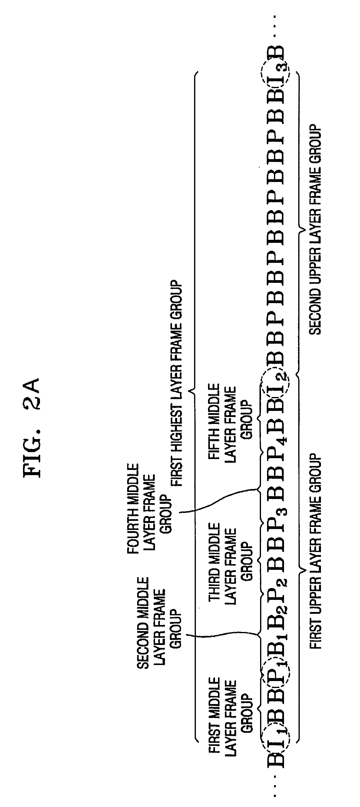
A method of and an apparatus for detecting video shot changes in a moving picture are provided. The method includes operations of: (a) examining whether there is a video shot change with respect to first through Kth (herein, K is a positive integer larger than 1) upper layer frame groups formed by combining video frames of a moving picture, first through Mth (herein, M is a positive integer larger than 1) middle layer frame groups formed by combining video frames in an Lth (herein, L is a positive integer larger than 1 and smaller than K) upper layer frame group of the first through Kth upper layer frame groups, and an Nth (herein, N is a positive integer larger than 1 and smaller than M) lower layer frame group in the Nth middle layer frame group of the first through Mth middle layer frame groups; and (b) generating a video shot change list by using result of the operation (a). Accordingly, it is possible to detect video shot changes faster because the compressed stream data of the moving picture are processed distinctively and hierarchically, to prevent errors in detecting shot changes caused by light changes because the normalized correlation coefficient as well as the differential characteristic value based on color distribution is used as a detection characteristic value, and to effectively detect shot changes with respect to analogous color distributions

Description

CROSS-REFERENCE TO RELATED APPLICATIONS [0001] This application claims the benefit of Korean Patent Application No. 10-2004-0014952, filed on Mar. 5, 2004, in the Korean Intellectual Property Office, the disclosure of which is incorporated herein by reference. BACKGROUND OF THE INVENTION [0002] 1. Field of the Invention [0003] The present invention relates to detection of video shot changes in moving picture data, and more particularly, to a method of detecting video shot changes in a moving picture by classifying video frames in units of multi-layer hierarchical streams and detecting the video shot changes with a high speed in order to rapidly index contents of the moving picture, and an apparatus using the same. [0004] 2. Description of the Related Art [0005] A video shot is a set of video frames captured continuously by a single camera movement while shooting a video. A video shot is used as a basic processing unit when indexing the video by theme. Techniques for detecting video ...

Claims


Application Information

Patent Timeline
Patent Type & Authority Applications(United States)
IPC IPC(8): H04N5/91G06T7/40G11B27/30H04N5/14H04N19/50H04N19/503H04N19/577H04N19/61H04N19/625
CPCG11B27/3081H04N5/147H04N19/87H04N19/61H04N19/142H04N19/00B23Q11/1084B23Q11/005B23Q11/0064
Inventor MOON, YOUNGSUKIM, JIYEUN
Owner SAMSUNG ELECTRONICS CO LTD
Learn More