
Transparent link layer mesh router

a mesh router and transparent technology, applied in the field of communication network data packet routing, can solve the problems of physical wire constraints limiting the distance, accessibility and mobility of wired clients, and no comprehensive network solution that provides high mobility, and achieves the effect of ease of deploymen

Inactive Publication Date: 2005-09-08
CHANG IND INC
View PDF7 Cites 13 Cited by
  • Summary
  • Abstract
  • Description
  • Claims
  • Application Information

AI Technical Summary

Benefits of technology

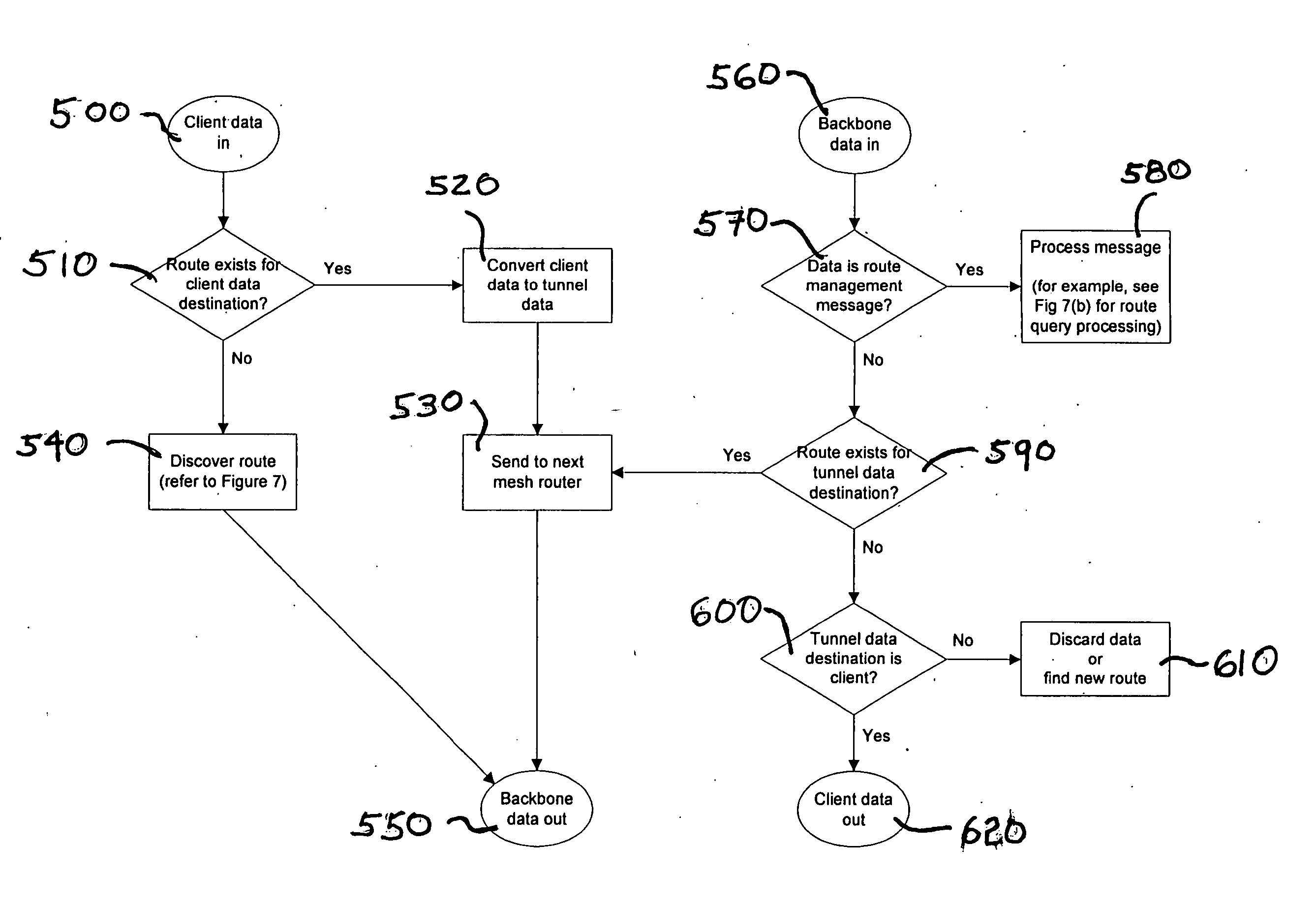
[0011] The present invention comprises a method and apparatus for transparent mesh routing in a communications network. By implementing transparent mesh routers at the link-layer of the network hierarchy, the routers can be easily deployed in the network without having to reconfigure or add client-side drivers to the networked clients. The present invention uses L2 (Link Layer) for route initiation and active client discovery and a combination L2 and L3 (Network Layer) for passive client discovery. By responding to data packets on Link Layer, networks composed of these transparent mesh routers require neither configuration by the network operator nor any pre-configuration of the network clients. The present invention is able to accomplish link layer route initiation without the need to implement a custom network stack (i.e., the invention utilizes the existing network architecture).
[0012] The mesh routers are transparent, in that, they allow clients to access other clients without any knowledge of the routing device being used. The transparent mesh router is capable of dynamically discovering clients and routing data packets to other clients in the network. The transparent mesh router adds efficiency to networked communication because it does not require that all communications be sent to a home node prior to being re-sent to a networked client (as in Mobile IP). In the transparent mesh router environment the networked clients may be mobile or fixed. The transparent mesh router will maintain connectivity between mobile clients with minimal interruption via a self-healing routing algorithm. The transparent mesh router is capable of communicating with other transparent mesh routers via either a wired or wireless backbone. In addition, the transparent mesh router is capable of medium to long-haul wireless connections, allowing for routers to be spaced apart in the range of miles or kilometers.
[0023] As such the present invention provides for a network router and means for network routing that impart a wide-range LAN having high-mobility and ease in deployment. By implementing transparent mesh routers at the link layer of network hierarchy, clients can interface with the network transparently, without having to be configured for the network and without having to implement network-related initiation software. In addition, the clients and the routers may be mobile devices that can function without the risk of service interruption. The use of the mesh routers provides long range routing in the LAN environment that limits the amount of hardware that needs to comprise the overall network.

Problems solved by technology

If wired switches, bridges and routers are implemented, range is typically limited and numerous devices are needed to construct the network.
Currently, there is no comprehensive network solution that provides high mobility as well as ease of deployment.
In the wired LAN environment, while the clients may be physically detached from one part of the LAN and re-attached elsewhere with minimal interruptions, physical wire constraints limit the distance, accessibility and mobility of wired clients.
However, IPv6 is still in a developmental step and the adoption of a standard for mobility for IPv4 is still speculative.
Currently, most wireless devices, such as wireless routers, wireless bridges, wireless access points and the like do not implement any type of mesh networking.
While the 802.11 standard for these devices does not specifically forbid mesh operation, it also does not implicitly allow mesh operation of the wireless devices.
However, since bridges and access points must be wired together, this limits the ease of deployment of the system and limits the physical size of the network.
However, implementation of link layer routing, and specifically link layer mesh routing, has been hampered by the fact that such use requires a cost-prohibitive custom network stack that would not be supported by existing network architecture.

Method used


Image

  • Transparent link layer mesh router
  • Transparent link layer mesh router
  • Transparent link layer mesh router

Examples


Embodiment Construction

[0035] The present inventions now will be described more fully hereinafter with reference to the accompanying drawings, in which some, but not all embodiments of the invention are shown. Indeed, these inventions may be embodied in many different forms and should not be construed as limited to the embodiments set forth herein; rather, these embodiments are provided so that this disclosure will satisfy applicable legal requirements. Like numbers refer to like elements throughout.

[0036] The present invention comprises methods, apparatus and systems for transparent mesh routing in a communications network. The routers are transparent, in that, they allow clients to access other clients without any knowledge of the routing device being used and without the need to reconfigure the accessing clients. The transparent aspect of the mesh router is realized by its ability to dynamically discover clients and route data packets to other clients in the network.

[0037]FIG. 4 is a schematic illust...


PUM


Abstract

The invention includes network mesh routers and methods for network mesh routing that are capable of transparently routing data packets to other clients on the network. The invention uses the link layer (L2) for route initiation and active client discovery and a combination L2 and the network layer (L3) for passive client discovery. By responding to packets on L2, networks composed of transparent mesh routers require neither configuration by the network operator nor any pre-configuration of the network clients.

Description

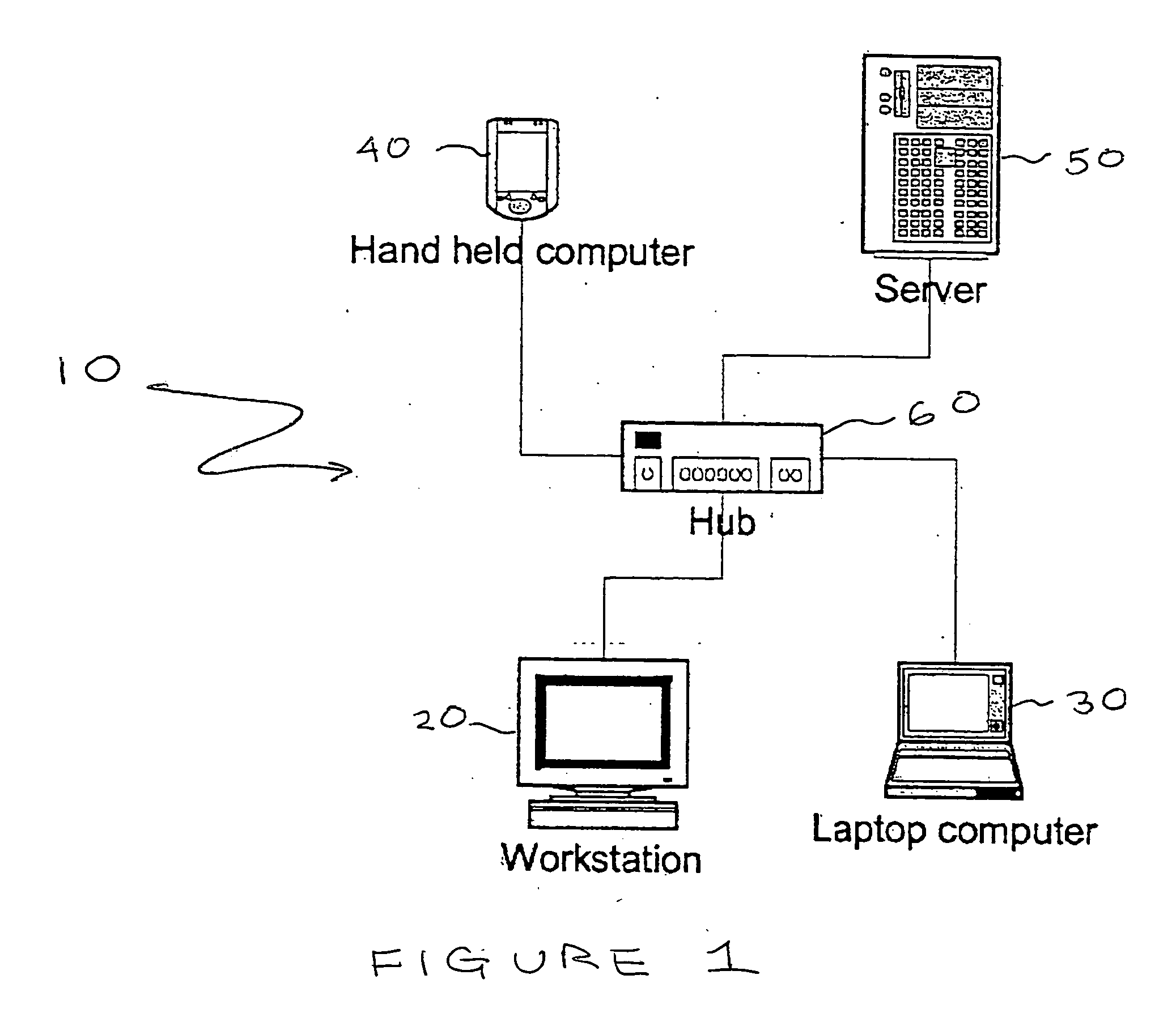
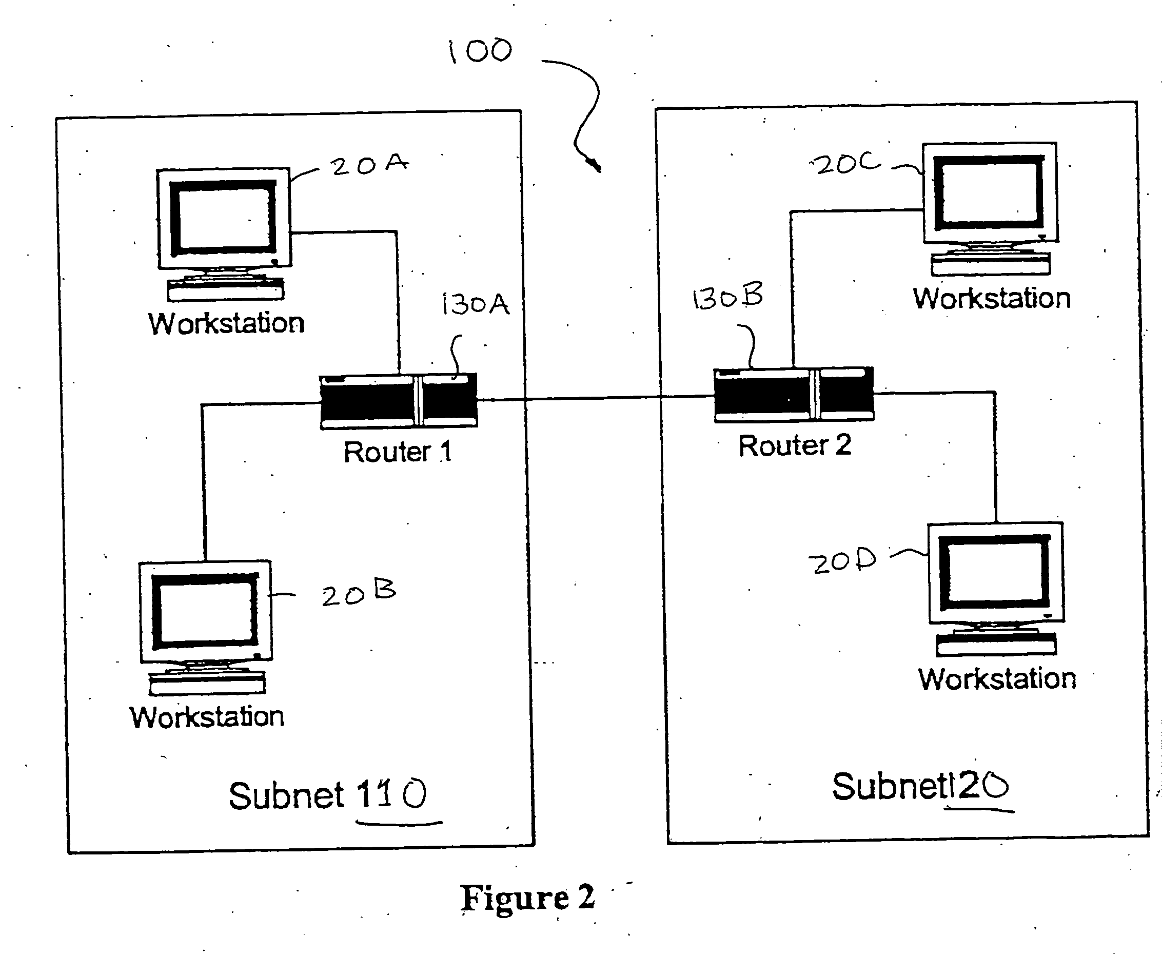
FIELD OF THE INVENTION [0001] The present invention relates to methods, apparatus and systems for communication network data packet routing and more specifically to methods, apparatus and systems for transparent link layer mesh routing in a communication network. BACKGROUND OF THE INVENTION [0002] Currently, Local Area Network and Wireless Local Area Network (LAN / WLAN) architecture is composed of network switches, bridges, hubs, routers, wireless access points, and wired and wireless clients. These devices all provide a certain degree of mobility and ease of deployment. Mobility allows the user of a wireless client, such as laptop computer, hand held device or the like to remain actively connected to the network while mobile. It is also possible to impart mobility to other wireless network devices such as switches, bridges, hubs, routers and the like. Ease of deployment is defined by ease of which clients can participate in the network; the less need to reconfigure the client or imp...

Claims


Application Information

Patent Timeline
Patent Type & Authority Applications(United States)
IPC IPC(8): H04L12/28H04L12/56
CPCH04L45/00H04W40/28H04W40/02
Inventor SUNG, DANNY TE ANMERGENTHAL, WADE D.WONG, SIMONJOHNSON, MICHAEL A.
Owner CHANG IND INC
Learn More