
Apparatus and method for processing synch signals in graphic controllers

a graphic controller and analog signal technology, applied in the field of display devices, can solve the problems of processing modules making errors in computing the wrong resolution of input signals, and misinterpreting glitches

Active Publication Date: 2005-09-08
GENESIS MICROCHIP
View PDF5 Cites 2 Cited by
  • Summary
  • Abstract
  • Description
  • Claims
  • Application Information

AI Technical Summary

Benefits of technology

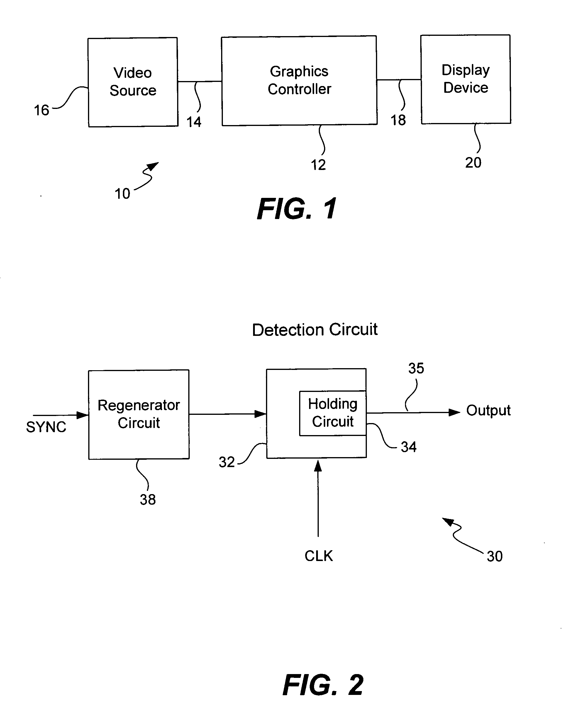
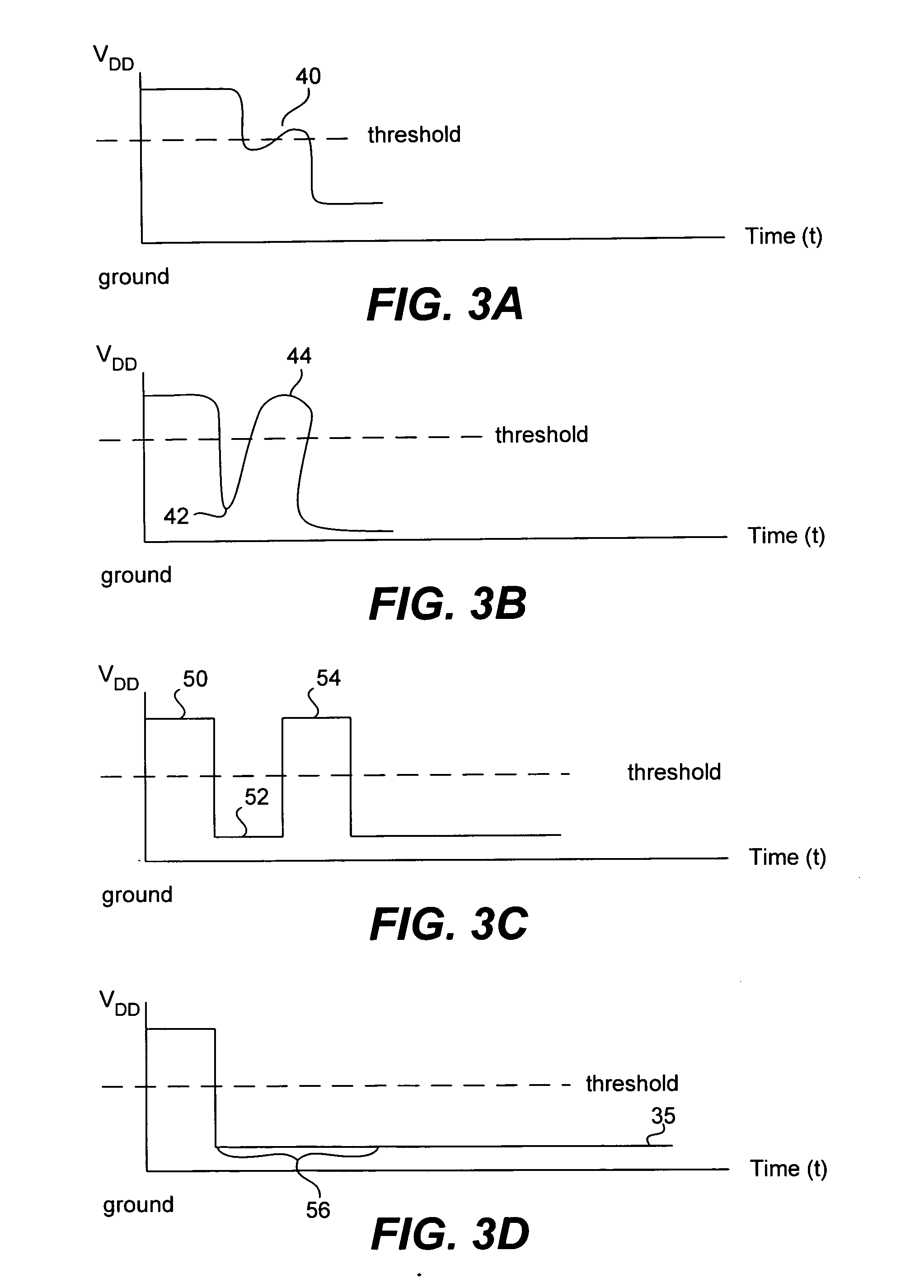
[0008] To achieve the foregoing, and in accordance with the purpose of the present invention, an apparatus and method for processing Hsync and Vsync signals in graphic controllers to avoid a false reading of pulses caused by glitches is disclosed. The apparatus includes a detection circuit having a first input configured to receive a first sync signal at either a first voltage corresponding to first state or a second voltage corresponding to a second state and a first output configured to generate an output signal at either the first voltage corresponding to the first state or the second voltage corresponding to the second state. The detection circuit also includes a first holding circuit configured to hold the first output of the detection circuit at either the first voltage or the second voltage for a predetermined period of time after the first synch signal first initially crosses a threshold voltage. The first holding circuit is configured to ignore any subsequent measured transitions of the first synch signal across the threshold during the predetermined period of time. During operation, the method involves detecting when the synch signal crosses the threshold for the first time. When this occurs, the output of the detection circuit is held at the appropriate state for the predetermined period of time, even if subsequent transitions across threshold occur during this period. After the predetermined period expires, the output is released and may assume the same state as the input sync signal at that time. In this manner, a misinterpretation of the resolution format caused by the reading of a “false” pulse caused by a glitch on a sync signal can be avoided.

Problems solved by technology

Glitches in the Hsync and / or Vsync signals provided to the inputs of the graphic controller may cause the processing module to make an error in computing the wrong resolution of the input signals.
The processing module may therefore misinterpret a glitch as a “false pulse”, and as a consequence, compute the wrong resolution of the input.

Method used


Image

  • Apparatus and method for processing synch signals in graphic controllers
  • Apparatus and method for processing synch signals in graphic controllers
  • Apparatus and method for processing synch signals in graphic controllers

Examples


Embodiment Construction

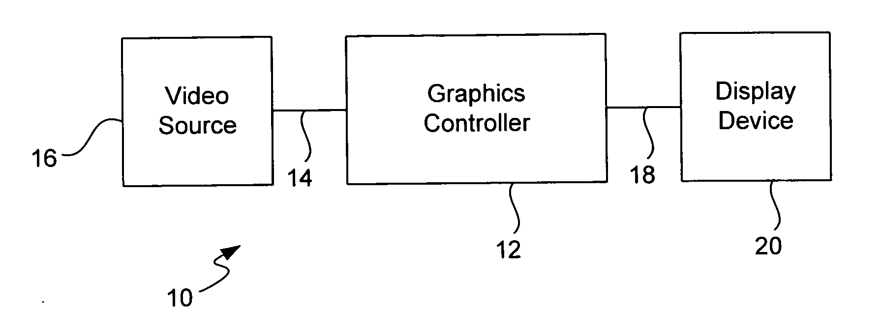
[0015] Referring to FIG. 1, a block diagram of a video display system according to the present invention is shown. The system 10 includes a graphics controller 12 configured to receive video input signals 14 from a video source 16 and to provide output video signals 18 to a display device 20. In various embodiments of the invention, the video input source can be any one of a number of different types, including a computer, video game console, television, or the like. Similarly, the display device 20 can also be anyone of a number of different types of display devices, such as a standard television, computer CRT display, LCD panel or a plasma display. The video input signals 14 include (but are not limited to) RGB color signals and Hsync and Vsync timing signals. The video output signals 18 include (but are not limited to) RGB color signals, Hsync and Vsync timing signals, a clock signal and a data enable DE signal.

[0016] The graphics controller 12 is responsible for translating the...


PUM


Abstract

An apparatus and method for processing Hsync and Vsync signals in graphic controllers to avoid a false reading of pulses caused by glitches. The apparatus and method involve detecting when the synch signal crosses the threshold for the first time. When this occurs, the output of the detection circuit is held for the predetermined period of time, even if subsequent transitions across threshold occur during this period. After the predetermined period expires, the output is released and may assume the same state as the input sync signal at that time. In this manner, a misinterpretation of the resolution format caused by the reading of a “false” pulse caused by a glitch on a sync signal can be avoided.

Description

FIELD OF THE INVENTION [0001] The present invention relates generally to the display devices, and more particularly, to an apparatus and method for processing Hsync and Vsync signals in graphic controllers. BACKGROUND OF THE INVENTION [0002] Graphic controllers are used by computers and other graphic-intensive devices such as video game consoles for controlling the image that is displayed on an image device, such as a CRT, LCD panel, or plasma display. Generally speaking, graphic controllers are responsible for translating information received in one resolution to a second resolution that is native to the display device. For example, if the video input signals are in the standard video 640×480 pixel resolution, but the actual display device is an HDTV display resolution having 1024×784 pixels, then the graphics controller is required to upscale the input video information to the 1024×784 format used by the display device. Alternatively, the graphics controller is required to downsca...

Claims


Application Information

Patent Timeline
Patent Type & Authority Applications(United States)
IPC IPC(8): G09G3/36
CPCG09G5/006G09G2360/02G09G5/363G09G5/18
Inventor CHILUKURI, RAMPRATHER, LAWRENCE A.VENUTHURUPALLI, RAMAKRISHNA R.
Owner GENESIS MICROCHIP
Learn More