
Apparatus for sensing angular position

a technology of angular position and apparatus, which is applied in the direction of galvano-magnetic hall-effect devices, instruments, galvano-magnetic devices, etc., can solve the problems of inability to detect the position of the object, so as to achieve the effect of improving the linear response of the sensor

Inactive Publication Date: 2005-09-08
DELPHI TECH INC
View PDF12 Cites 5 Cited by
  • Summary
  • Abstract
  • Description
  • Claims
  • Application Information

AI Technical Summary

Benefits of technology

[0007] Aspects of the invention employ a cost effective magnetic configuration that may include only one magnet. Sensor redundancy may easily be achieved without the need of additional magnetic flux producing or flux carrying components such as magnets or concentrators since the raw magnetic signal has symmetry. This symmetry allows the use of a Hall-device on either side of the magnet.

Problems solved by technology

Such sensors can have reliability problems due to the susceptibility of the resistance-strips to premature wear.
Also, the vibration of contact brushes along the resistance-strips may cause unacceptable electrical noise in the output signals.
When flux concentrators are not used, the geometrical shapes of the magnetic sources may become complex.
Also, the geometrical shapes of the concentrators themselves are often complex.
As with any other component, geometrical complexity increases the cost associated to produce such component and obviously drives the total component and manufacturing costs of the respective sensor assembly.
Those sensors utilizing concentrators and requiring low hysterisis are typically the most expensive because of the special material required.
Typically, the wider the application ranges of rotation, the higher the cost of the sensor system.

Method used


Image

  • Apparatus for sensing angular position
  • Apparatus for sensing angular position
  • Apparatus for sensing angular position

Examples


Embodiment Construction

[0018]FIG. 1 illustrates a prior art sensing device 10 that uses a dual magnet array. Device 10 includes a first magnet 12 and a second magnet 14 that create a magnetic field that changes as the magnets are rotated about a sensing element 16. Sensing element 16 is positioned between two magnets 12, 14 and may detect the amount of flux lines crossing perpendicular to the sensing element 16. The field distribution detected by sensing element 16 may yield a response that somewhat approximates a linear response. However, it has been determined that by using a single magnet, shaping it to a specific geometry and determining certain other sensor system design parameters as a function of the magnet's shape, a more linear output from a sensing element may be obtained than the sensing device 10 of FIG. 1.

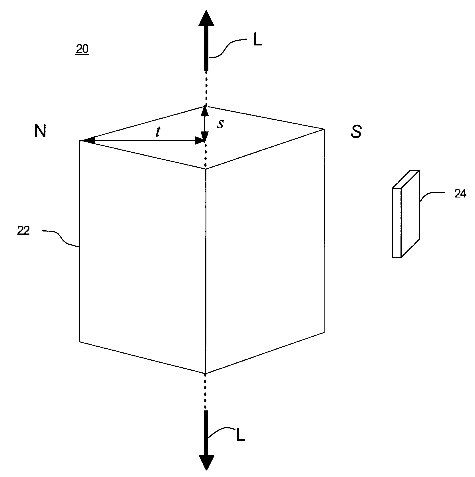
[0019]FIG. 2 illustrates a schematic of an exemplary embodiment of a sensor system 20 in accordance with aspects of the invention. One aspect allows for sensor system 20 to include an exemp...


PUM


Abstract

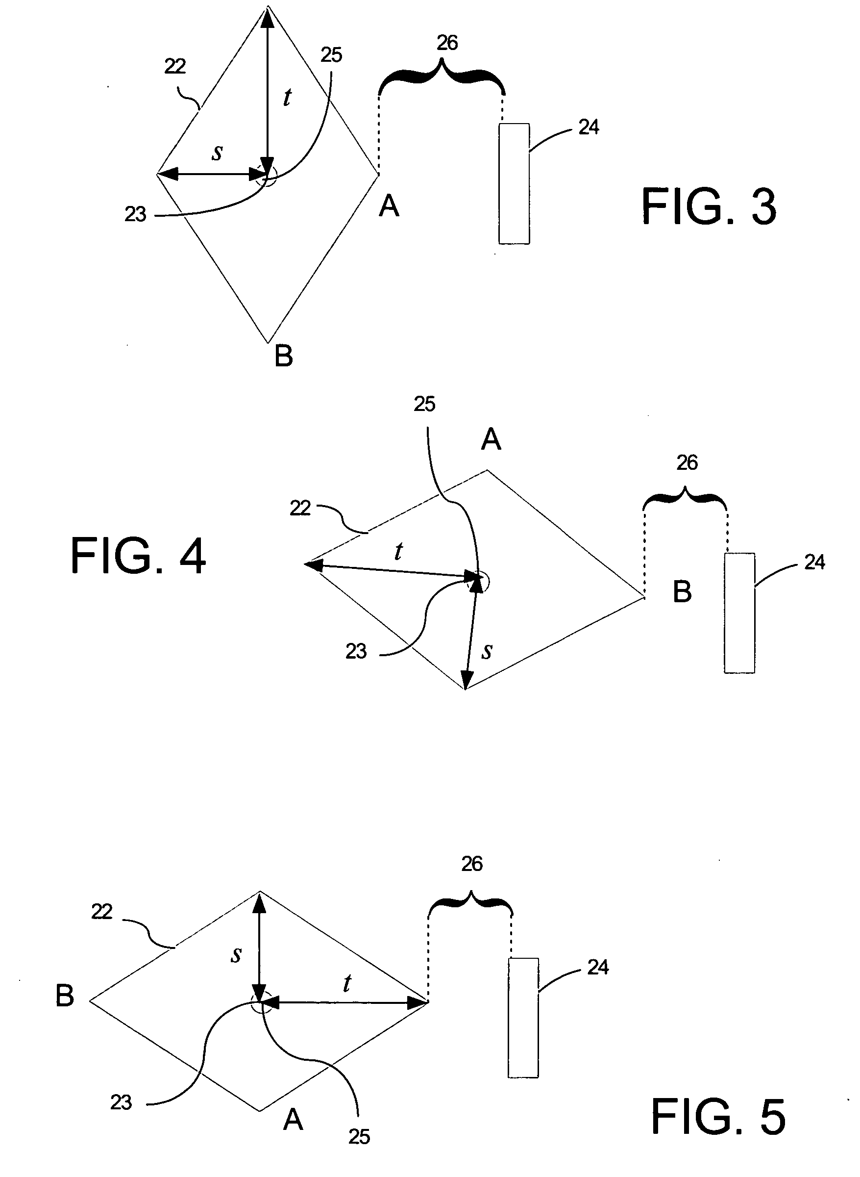
An apparatus for sensing a position of an object is provided that may include a magnet having a set of magnetic flux properties, the magnet mounted for movement about an axis relative to the object and a magnetic field-sensing device mounted in fixed relation to and spaced from the magnet, the magnetic field-sensing device calibrated to sense a change in at least one magnetic flux property in response to movement of the magnet relative to the object and generate a data signal indicative of a position of the object. In one aspect the magnet is configured to have a substantially diamond shaped cross section and the magnetic field-sensing device is calibrated to sense a change in flux density distribution in response to a change in an air gap defined between an exterior surface of the magnet and the magnetic field-sensing device.

Description

CROSS REFERENCE TO RELATED APPLICATIONS [0001] This application is related to a U.S. patent application filed on even date herewith having Attorney Docket Number DP-310779 and Application Ser. No. ______, which is specifically incorporated herein by reference. FIELD OF THE INVENTION [0002] The present invention relates in general to angular position sensors and in particular to a sensor using a magnet shaped for reducing nonlinearity. BACKGROUND OF THE INVENTION [0003] Some motor vehicle control systems require angular position sensors that need only sense partial angular motion of one part relative to another part, e.g., less than plus or minus ninety degrees. Shaped magnets have been used in conjunction with magnetic field sensors in order to provide non-contact angular position sensors that sense partial angular motion. Angular position sensors utilizing rotating magnets sensed by stationary magnet field sensors typically produce a sinusoidal or pseudo-sinusoidal output signal. T...

Claims


Application Information

Patent Timeline
IPC IPC(8): G01D5/14
CPCG01D5/145G01D2205/77
Inventor MARTINEZ, DANIEL A.GODOY, ARQUIMEDESALMARAZ, JOSE L.
Owner DELPHI TECH INC
Learn More