
Wireless controller with gateway

a controller and gateway technology, applied in the field of utility consumption control, can solve the problems of affecting utility costs, large variance in total demand on the network, and increase in the cost of providing a utility, and achieve the effect of facilitating the control of hvac equipmen

Inactive Publication Date: 2005-09-08
HONEYWELL INT INC
View PDF25 Cites 312 Cited by
  • Summary
  • Abstract
  • Description
  • Claims
  • Application Information

AI Technical Summary

Benefits of technology

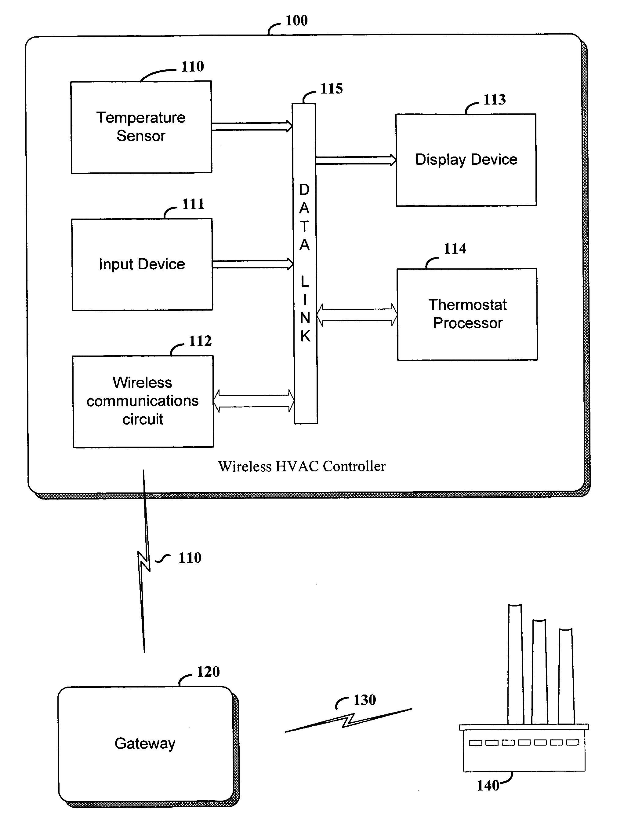
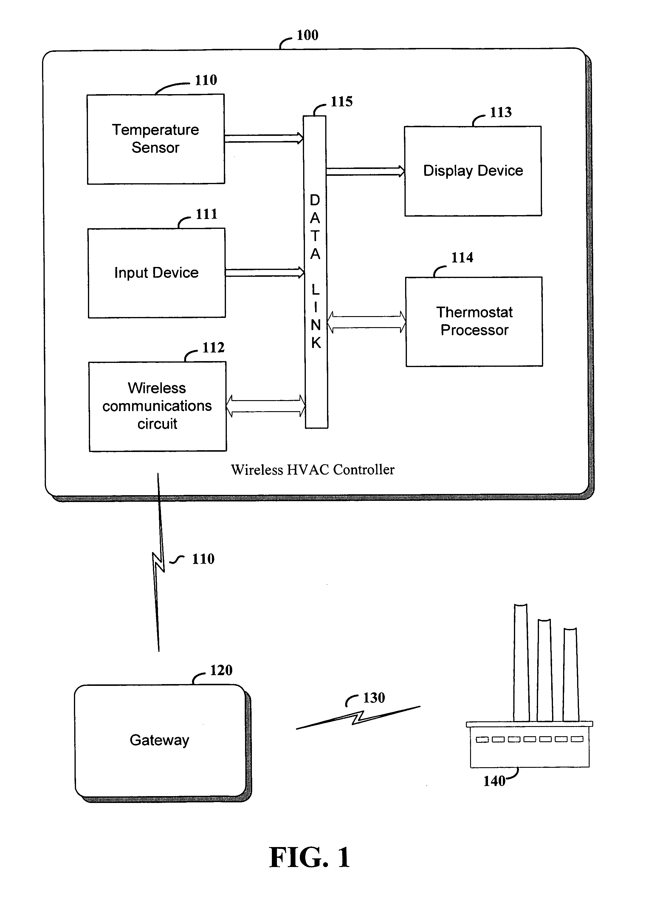
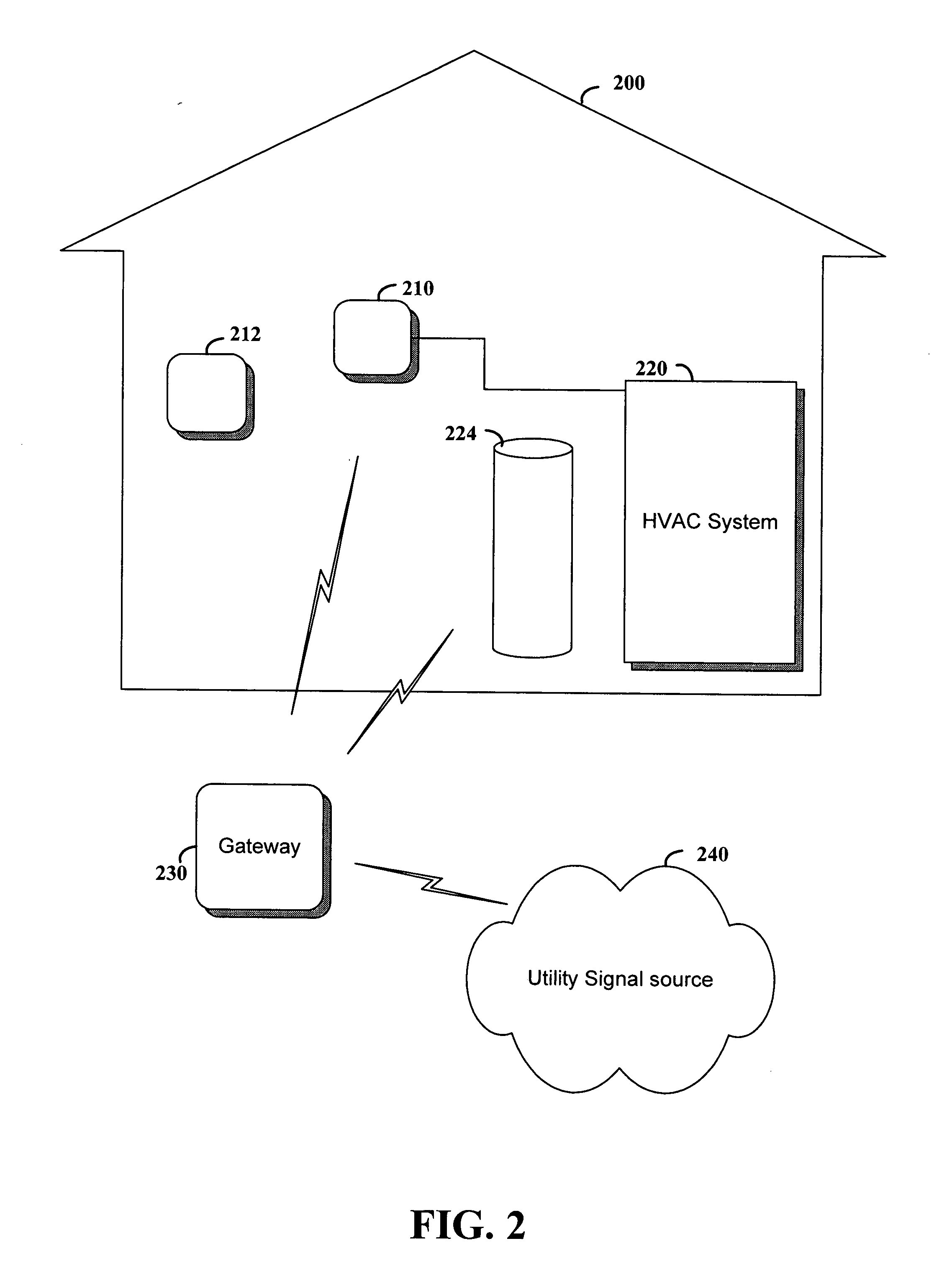
[0009] In accordance with one example embodiment of the invention, a wireless communications device is configured and arranged to control energy-consuming equipment in response to both local control inputs and wireless control inputs received from a gateway. The local control inputs are received, e.g., at the wireless communications device using an input device such as a keypad as is typically used for thermostats. The wireless control inputs originate from a location remote from the gateway, such as a utility provider that configures the control information as a function of one or more of a variety of characteristics or an end-user sending control inputs via the gateway to remotely control the energy-consuming equipment. With this approach, the control of local energy-consuming devices can be effected without necessarily coupling a controller directly to the energy-consuming devices and, in some instances, without necessarily accessing premises at which the energy is consumed. For instance, by wirelessly communicating between a utility gateway and a thermostat wired to an HVAC system, the gateway does not necessarily have to directly couple to the HVAC system.
[0010] In a more particular example embodiment of the present invention, the wireless communications device includes a thermostat and circuitry for providing control signals to HVAC equipment using, for example, conventional wired connections commonly used in thermostat applications. The thermostat includes a keypad type device for receiving user inputs at the thermostat for use in controlling the climate in an environment. A wireless transceiver at the wireless communications device communicates with the gateway for passing signals between the gateway and the thermostat, with signals received from the gateway being used to control the HVAC equipment. As with the example embodiment discussed above, this approach facilitates the control of HVAC equipment with control signals sent via the gateway and without necessarily coupling the gateway directly to the HVAC equipment.

Problems solved by technology

One challenge confronting such utility providers today is the great variance in total demand on a network between peak and off-peak times during the day.
For instance the cost of providing a utility can increase during peak supply times due to a variety of conditions.
The efficiency of power generation or fuel supply equipment, limitations in a utility distribution network, economical cost / demand relationships and other factors all affect utility costs.
The overriding control functions cause the setpoint to change to use less power or fuel at times of high demand or high unit cost.
In addition, typically installations of this type often require a significant amount of technician time, which can be expensive.
Accordingly, the above-discussed issues have been challenging to the implementation of a variety of devices and systems involving climate control and particularly involving the control of HVAC and other equipment in response to price and / or demand conditions.

Method used


Image

  • Wireless controller with gateway
  • Wireless controller with gateway
  • Wireless controller with gateway

Examples


Embodiment Construction

[0019] In the following description, reference is made to the accompanying drawings which form a part hereof, and in which is shown by way of illustration particular embodiments in which the invention may be practiced. It is to be understood that other embodiments may be utilized, as structural and operational changes may be made without departing from the scope of the present invention.

[0020] According to an example embodiment of the present invention, a system controller installed, e.g., at a user-accessible controller location wirelessly communicates with a utility gateway for receiving control signals facilitating external utility control of an electrical and / or fuel-consuming system. The gateway responds to input received from a utility company source by wirelessly sending a control-type signal to the system controller. The system controller responds to the control-type signal by controlling the operation of equipment such as a furnace, air conditioner or water heater, for ins...


PUM


Abstract

Remote control of energy consumption is realized using a readily installable, flexible approach. According to an example embodiment of the present invention, a remote source communicates with a wireless controller for executing energy usage control. The remote source sends signals to the wireless controller via a gateway located near or, in one implementation, forming part of the wireless controller. In response to the signals, the wireless controller sets control settings for operating one or more of a variety of equipment types, such as a furnace, air conditioner, water heater or heat pump. With this approach, wired connections from the gateway to energy-consuming equipment do not necessarily need to be made in order to effect remote energy-consumption control. For instance, when used in connection with a controller wired to the energy-consuming equipment, the gateway need only communicate wirelessly with the controller and does not necessarily need to be coupled to the energy-consuming equipment. In addition, access to the energy-consuming equipment for establishing remote energy control is not necessary; rather, the remote energy control can be effected by accessing user-friendly locations, such as those where thermostats and other controllers are typically located.

Description

FIELD OF THE INVENTION [0001] This invention relates in general to utility consumption control, and more particularly to a controller with a local gateway for executing remote utility consumption control. BACKGROUND OF THE INVENTION [0002] Electronic controllers such as thermostats and fan controls are used to control a variety of heating, ventilating and air conditioning (HVAC) equipment as well as other fuel and power consumption equipment. Furnaces, heat pumps, gas burners, water heaters, electric radiators, water radiators, air conditioners, chillers, fans, blowers and humidity controllers are example types of equipment for which electronic controllers are used. These equipment types are often grouped into the category called “HVAC.” Controllers for these equipment types are often located in user-accessible locations that are remote from the controlled equipment. For instance, thermostats are commonly placed on interior walls of a dwelling and located remotely from controlled HV...

Claims


Application Information

Patent Timeline
Patent Type & Authority Applications(United States)
IPC IPC(8): G05D23/00
CPCF24F11/006G05B13/02F24F2011/0075F24F2011/0068F24F11/30F24F2110/00F24F2120/20F24F11/56F24F11/58F24F11/46F24F11/52F24F11/62F25B2600/07
Inventor TESSIER, PATRICK C.HARTZLER, JEFFREY S.
Owner HONEYWELL INT INC
Learn More