Wall mounted tool holder
a tool holder and wall mount technology, applied in the field of wall mount holder, can solve the problems of increasing the exterior size of the cleaner, reducing the thickness of the cleaner, and reducing the use efficiency of the cleaner, so as to reduce the thickness, reduce the thickness, and improve the use efficiency.
- Summary
- Abstract
- Description
- Claims
- Application Information
AI Technical Summary
Benefits of technology
Problems solved by technology
Method used
Image
Examples
first embodiment
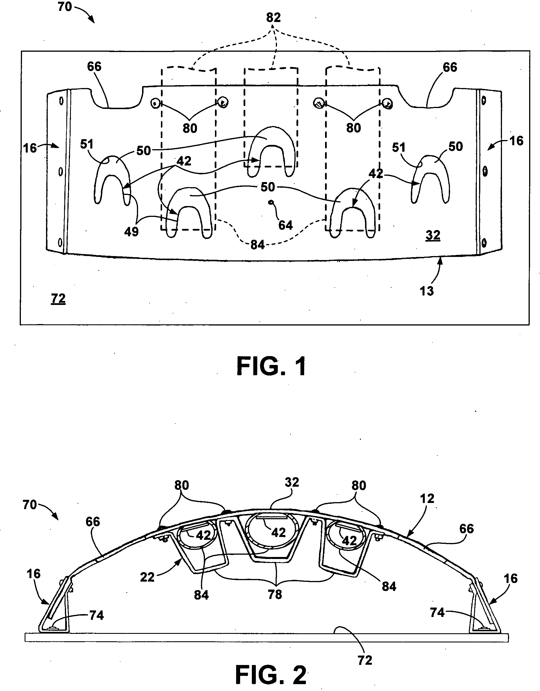
[0037]FIGS. 1, 2 and 3 illustrate a first embodiment tool holder 70 mounted on a vertical flat or finished wall 72. Holder 70 includes a body 13 and two support preforms 16, previously described. Body 13 is identical to body 12 but without outer hinges 36 or mounting panels 40.
[0038] The holder is mounted on the wall 72 by mounting both support preforms 16 on the wall with hinges 60 extending vertically. The mounting panels 56 are then attached to the wall 72 by appropriate fasteners 74 extending through openings 64 in the vertically oriented mounting panels 56. The two mounting panels 56 are spaced apart a predetermined distance so that panel 32 is bowed out from wall 72 as illustrated.
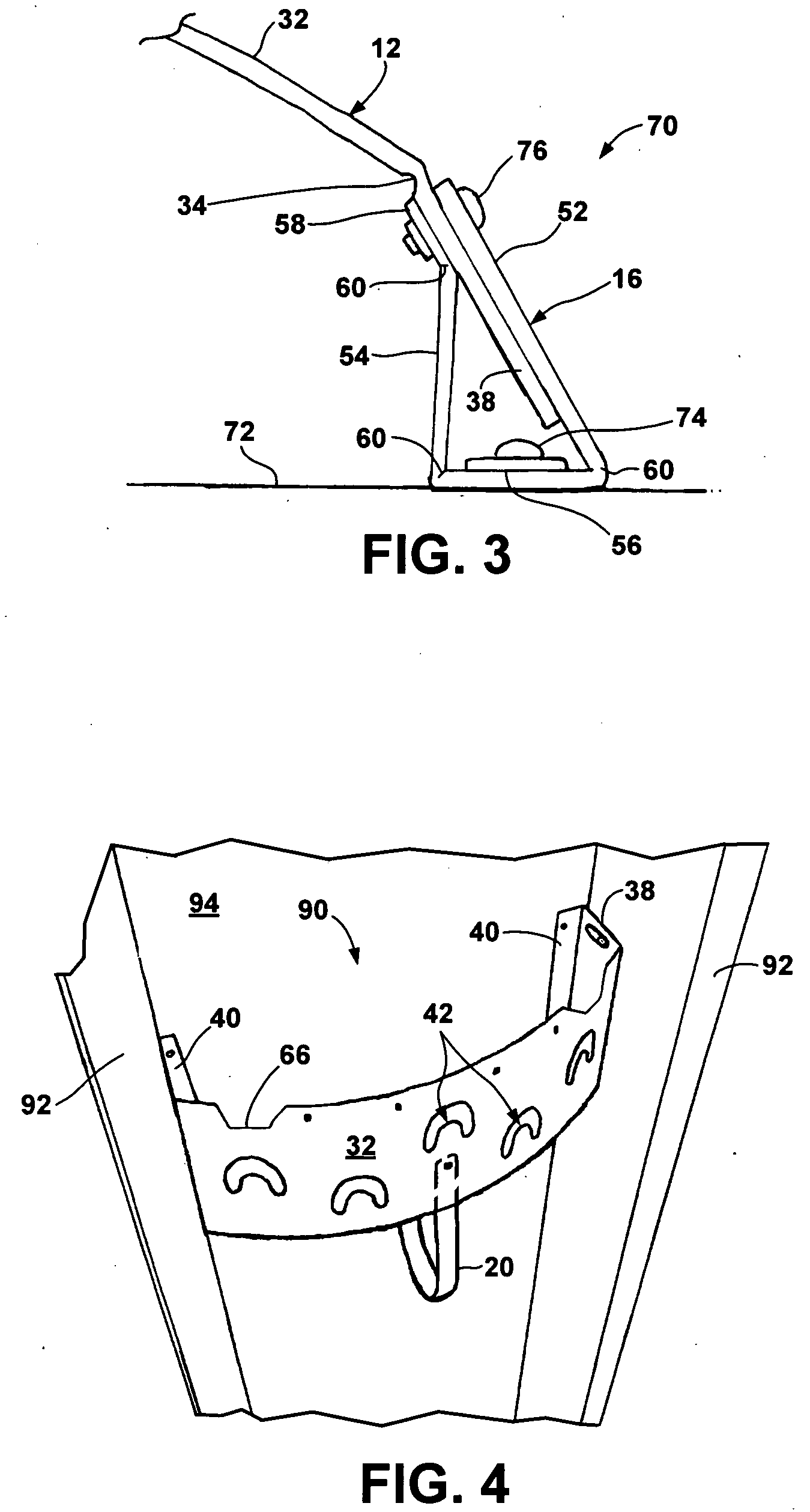
[0039] One of the panels 38 of body 13 is positioned adjacent the mounting panel 56 of one support preform and the support preform panels 52 and 54 are bent about hinges 60 away from wall 72 to capture or sandwich panel 38 between panels 52 and 54 as shown in FIG. 3. The attachment panel 58 is bent ...
second embodiment
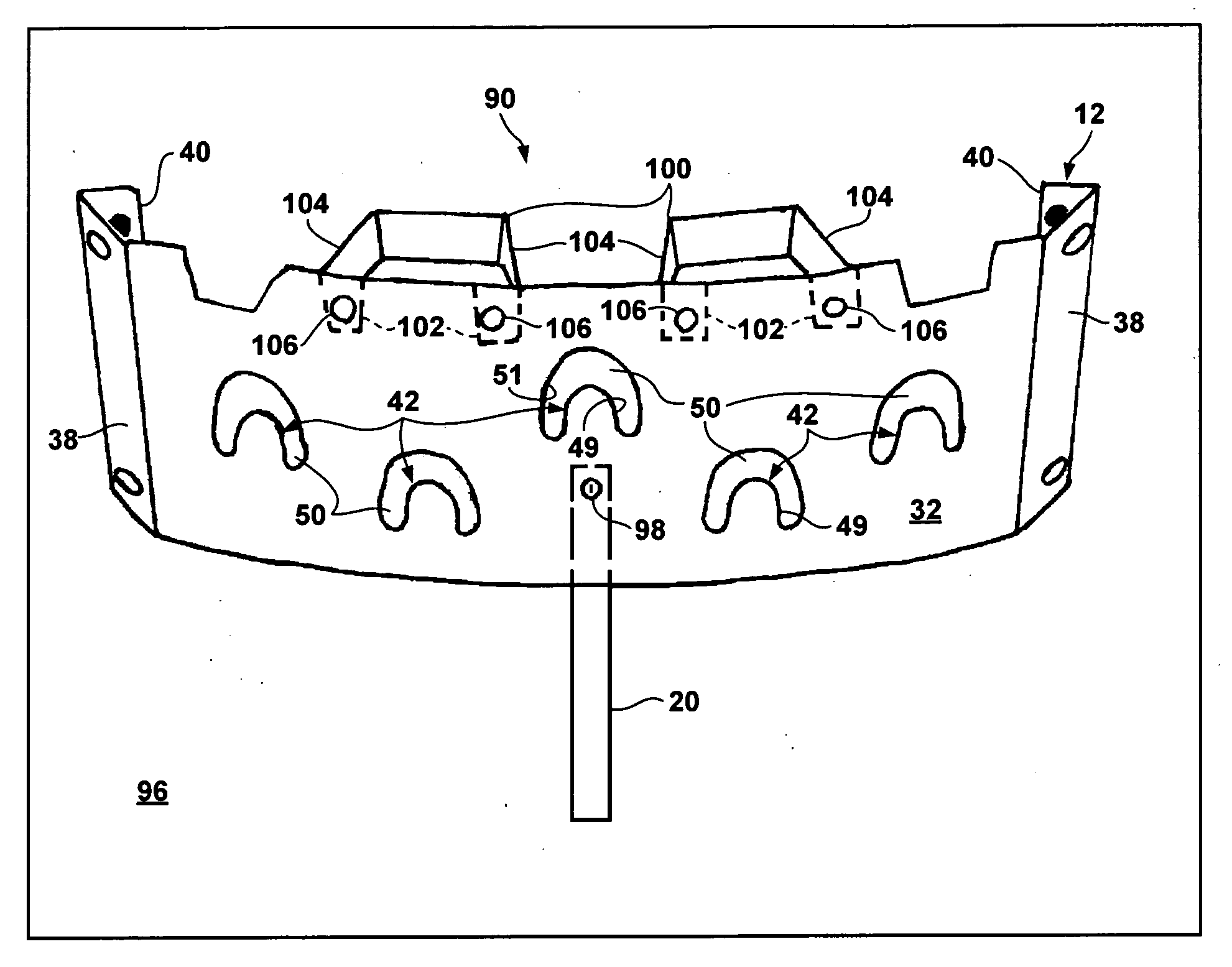
[0045] If desired, strap 20 may be formed into a loop and secured to the inner surface of panel 32 at mounting hole 64 located below central finger 42. Strap 20 forms a loop for supporting a coiled vacuum cleaner hose, as shown more clearly in FIGS. 4, 5 and 6. The strap extends straight down from hole 64 and bends inwardly from the panel to form a hose support loop 89 located on the convex side of the panel, between the panel and the adjacent wall. Loop 89 supports the hose behind the panel. The hose does not extend out from the panel. Hinge 91 on the inner end of the loop is flexed to locate loop 89 inside the panel.
[0046] Second embodiment tool holder 90 is illustrated in FIGS. 4-8. As shown in FIG. 4, holder 90 may be mounted between two vertical studs 92 extending to one side from unfinished wall 94. Alternatively, holder 90 may be mounted on flat finished wall 96 as shown in FIG. 5.
[0047] Holder 90 includes body 12 with a finger or central panel 32 and mounting panels 38 and ...
third embodiment
[0055]FIG. 12 illustrates a third embodiment tool holder 140 which is similar to holder 14 shown in FIG. 11. Holder 140 includes a central panel 142, like panel 32, and five tool retention fingers 144 and surrounding slots 146 having the same shape as fingers 42 and slots 50. The central finger 144 and surrounding slot 146 are identical to the finger 48 and slot 50 in the center of panel 32 with the lower ends of the slot and the base of the finger located on a horizontal line 148 parallel to the top and bottom edges 150 and 152. The fingers and slots to either side of the central finger 144 and slot 146 are tilted away from the central finger and slot proportional to the distance from the central finger and slot so that the finger bases and the lower ends of the slots lie on lines 154 and 156 with the inner end of the slot and finger base located above the outer end of the slot and finger base. The outward tilt of the outer fingers and slots is shown in FIG. 12. The outer fingers 1...
PUM
 Abstract
Description
Claims
Application Information
 - R&D
- Intellectual Property
- Life Sciences
- Materials
- Tech Scout
- Unparalleled Data Quality
- Higher Quality Content
- 60% Fewer Hallucinations
Browse by: Latest US Patents, China's latest patents, Technical Efficacy Thesaurus, Application Domain, Technology Topic, Popular Technical Reports.
© 2025 PatSnap. All rights reserved.Legal|Privacy policy|Modern Slavery Act Transparency Statement|Sitemap|About US| Contact US: help@patsnap.com


