
Damper assembly and washing machine using the same

a technology of damper assembly and washing machine, which is applied in the direction of washing machine with receptacles, shock absorbers, plastic/resin/waxes insulators, etc. it can solve the problems of bringing about the washing effect of beating and rubbing, the damper assembly as described above is difficult to be assembled to the tub and cabinet, and the pins tend to be abraded, so as to facilitate assembly work.

Inactive Publication Date: 2005-09-08
LG ELECTRONICS INC
View PDF3 Cites 6 Cited by
  • Summary
  • Abstract
  • Description
  • Claims
  • Application Information

AI Technical Summary

Benefits of technology

The present invention provides a damper assembly and a washing machine using the same that overcome limitations and disadvantages of the related art. The damper assembly includes a base plate, a body mounted with respect to the base plate, a damper, and a damper coupler for attenuating vibrations generated in the body. The damper includes a pair of first connectors with at least one first through hole for receiving one of the first pins, and the damper coupler includes a pair of second connectors with at least one second through hole for receiving the one of the first pins. The first and second through holes are aligned to allow insertion of the first pins, and the flared mouth of one of the second through holes guides the insertion of the first pins. The damper coupler also includes a pair of supports for respectively supporting opposite sides of each first connector. The technical effects of the invention include facilitating assembly work, preventing abrasion of pins, and reducing vibrations generated in the washing machine.

Problems solved by technology

A drum type washing machine avoids causing damage or ravel to the laundry, consumes less water, and brings about a washing effect of beating and rubbing.
The damper assembly as described above, however, is difficult to be assembled to the tub and cabinet.
In addition, after assembly, the pins tend to be abraded.

Method used


Image

  • Damper assembly and washing machine using the same
  • Damper assembly and washing machine using the same
  • Damper assembly and washing machine using the same

Examples


Embodiment Construction

[0025] Reference will now be made in detail to the preferred embodiments of the present invention, examples of which are illustrated in the accompanying drawings. Throughout the drawings, like elements are indicated using the same or similar reference designations where possible.

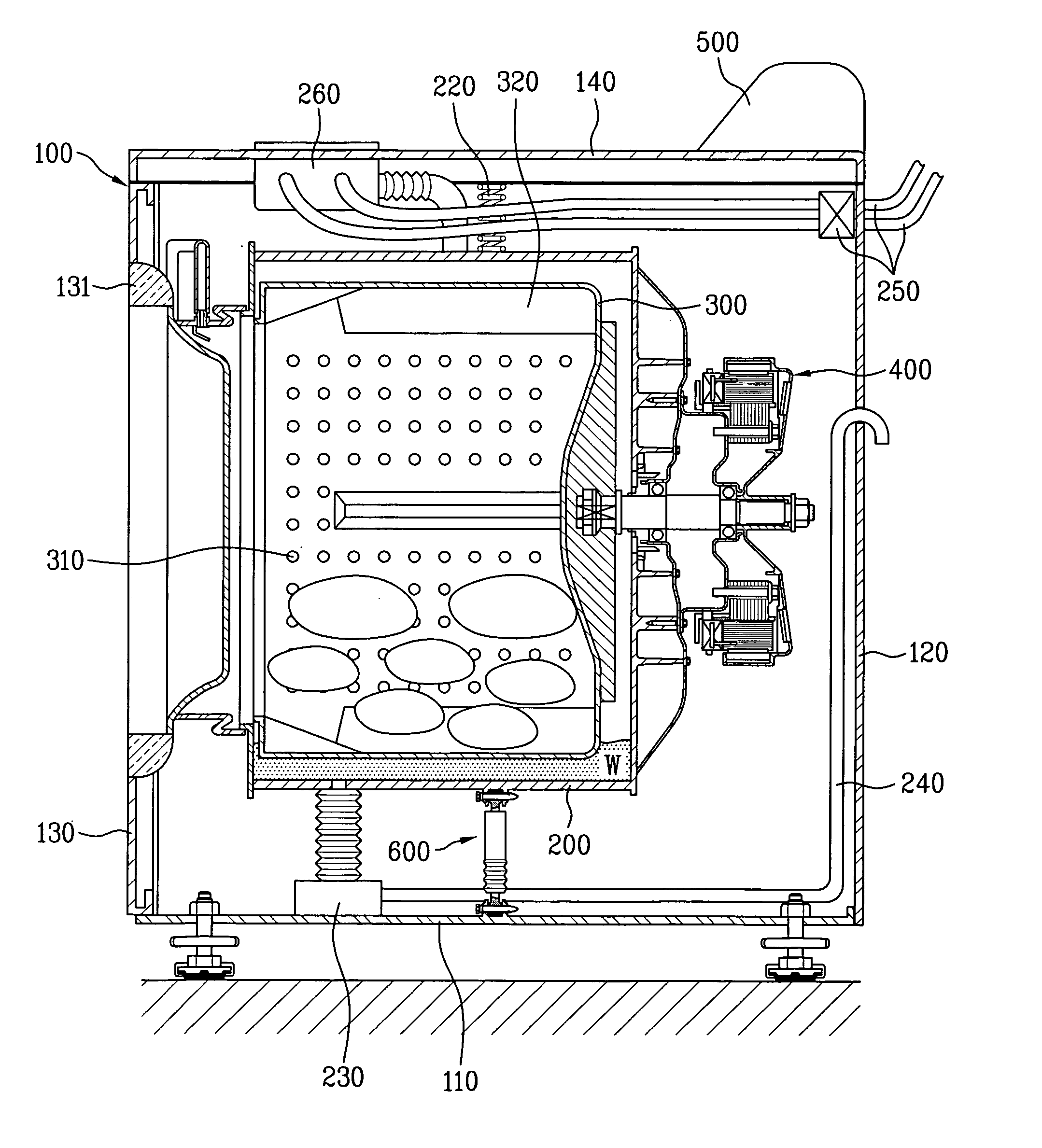
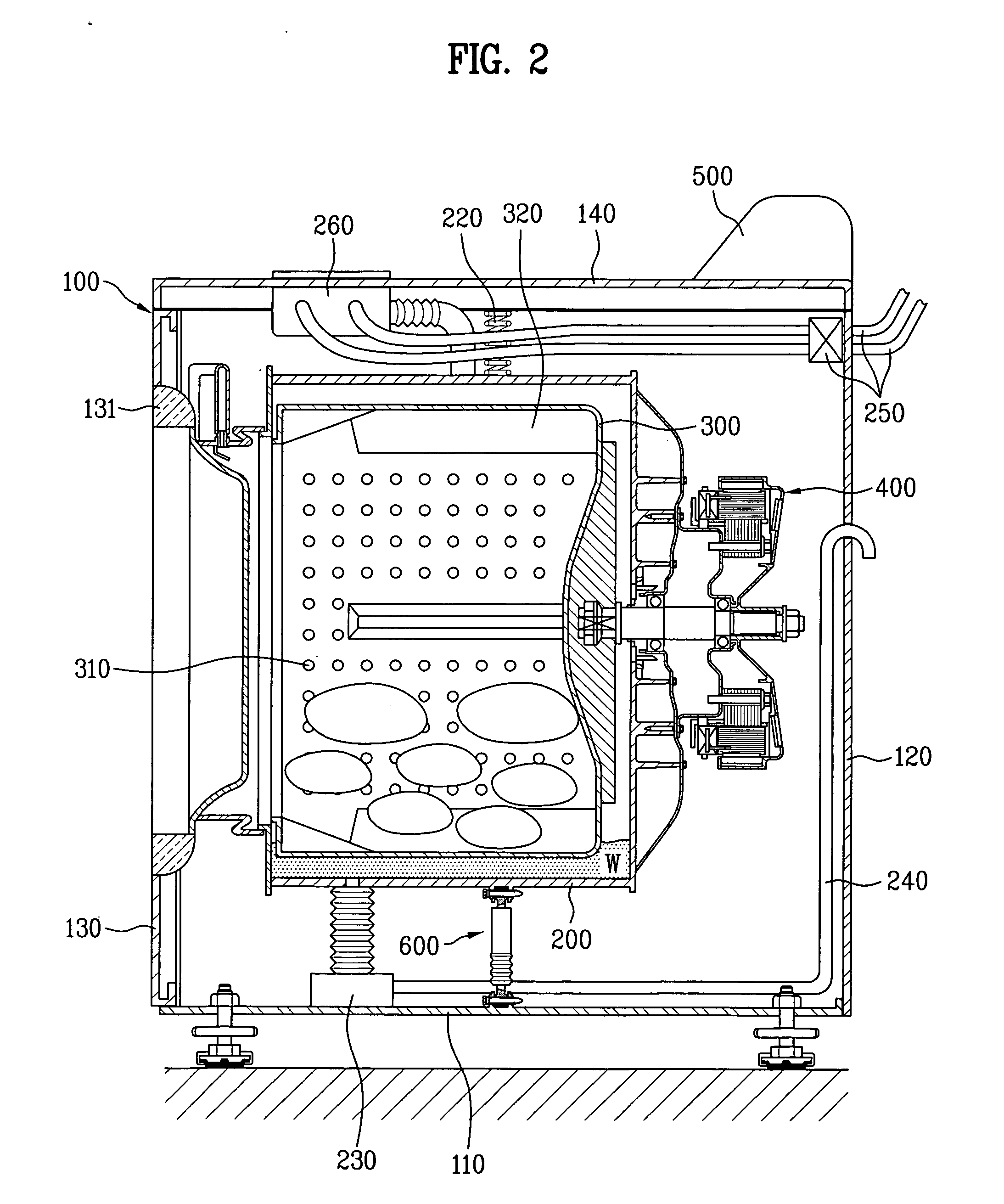
[0026] First of all, FIG. 2 is a cross-sectional diagram of a washing machine having a damper assembly according to the present invention and FIG. 3 is a cross-sectional diagram of a damper assembly according to the present invention. Referring to FIGS. 2 and 3, a drum type washing machine according to one embodiment of the present invention includes a cabinet 100 forming an exterior, a tub 200 provided within the cabinet 100, a drum 300 rotatably provided within the tub 200, and a rotating means 400 for rotating the drum 300. The cabinet 100 includes a base plate 110 provided to a bottom side, a pair of side plates (not shown) provided to both sides of the base plate 110, respectively, a rear plate 120 pro...


PUM

PropertyMeasurementUnit
mechanical energyaaaaaaaaaa
drive forceaaaaaaaaaa
frictionaaaaaaaaaa

Abstract

A damper assembly and a washing machine using the same are disclosed. The damper assembly includes a damper assembly includes a base plate, a body mounted with respect to the base plate, a damper, coupled between the base plate and the body, for attenuating a vibration generated in the body, and a damper coupler, the damper including a pair of first connectors, each first connector being integrally formed with one end of the damper and having at least one first through hole, a pair of second connectors integrally formed with each of the base plate and the body, respectively, and having at least one second through hole, and first and second pins for respectively fixing one of the first connectors into one of the second connectors, and wherein one of the at least one first through hole and the at least one second through hole has a flared mouth for guiding the insertion of the one of the first and second pins.

Description

[0001] This application claims the benefit of Korean Application No. P2004-013998, filed on Mar. 2, 2004, which is hereby incorporated by reference. BACKGROUND OF THE INVENTION [0002] 1. Field of the Invention [0003] The present invention relates to a washing machine, and more particularly, to a damper assembly and a washing machine using the same, by which a facilitating structure of assembly is provided. [0004] 2. Discussion of the Related Art [0005] Generally, the washing machine is an apparatus for removing filth or dirt attached to the laundry using the detergent and mechanical energy applied thereto appropriately. In such a washing machine, a tub holds water and detergent inside and a laundry is put in a drum installed within the tub. The drum is rotated to perform washing, rinsing, and dewatering. The drum, which is horizontally installed within a drum type washing machine, holds detergent, water, and laundry therein and is then rotated by a drive force of a motor to remove f...

Claims


Application Information

Patent Timeline
Patent Type & Authority Applications(United States)
IPC IPC(8): D06F29/00D06F37/22
CPCD06F37/22H01B11/18H01B1/02H01B3/30H01B5/12D06F39/125Y02B40/00
Inventor KWON, HO CHEOLPARK, SAM JESONG, HACK JAIKIM, BEOM JUNLIM, IL HYEOK
Owner LG ELECTRONICS INC
Learn More