
Aggregation of multiple headless computer entities into a single computer entity group

a headless computer and entity technology, applied in the computer field, can solve the problems of adding extra hardware, adding extra cost, inherent reliability reduction, etc., and achieve the effect of reducing the complexity of the architecture, and reducing the reliability of the system

Active Publication Date: 2005-09-01
HEWLETT-PACKARD ENTERPRISE DEV LP
View PDF11 Cites 38 Cited by
  • Summary
  • Abstract
  • Description
  • Claims
  • Application Information

AI Technical Summary

Problems solved by technology

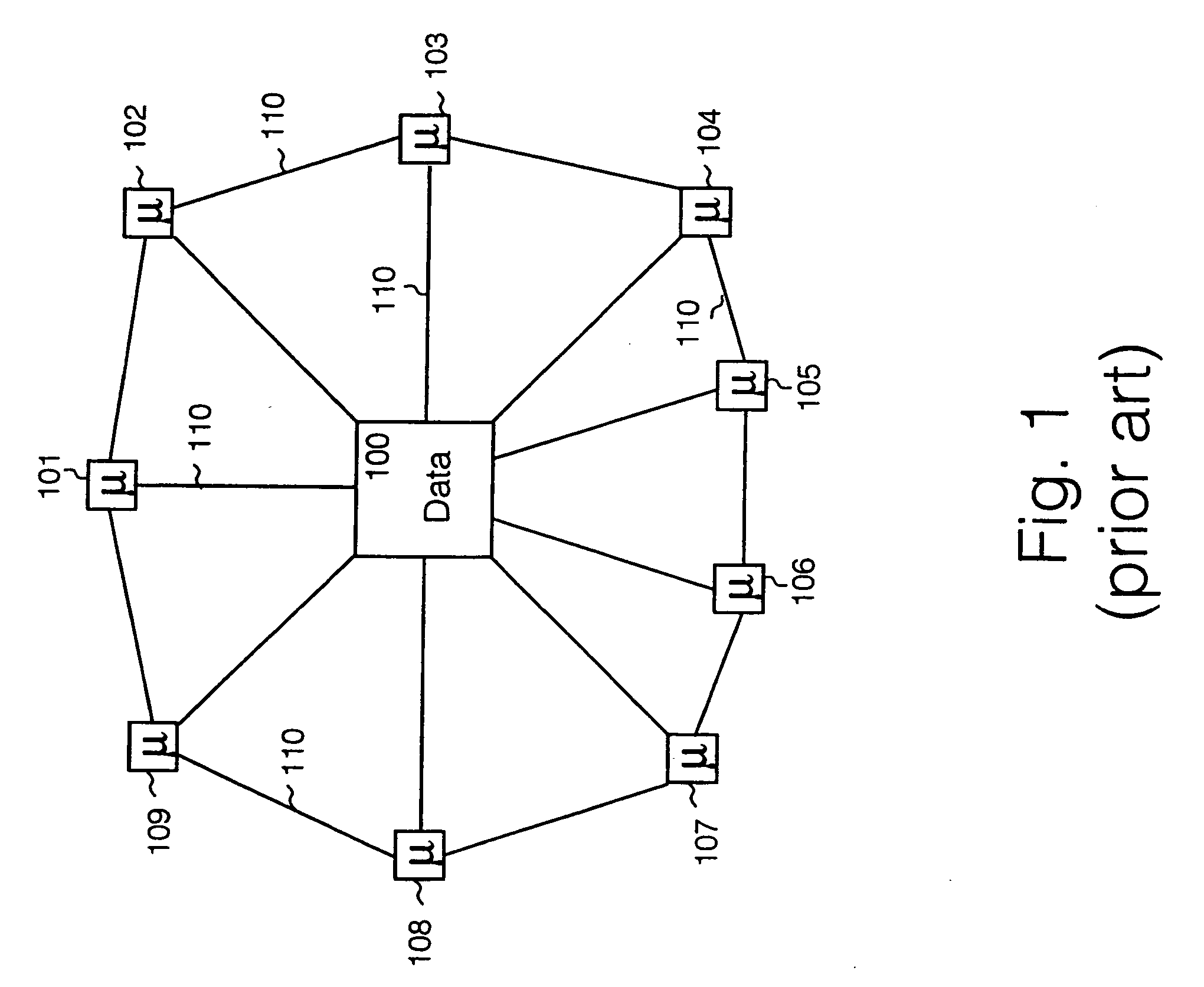
True clustering, where all the processor capacity, memory capacity and hard disk capacity are shared between computer entities requires a high bandwidth link between the plurality of computer entities, which adds extra hardware, and therefore adds extra cost.
Also there is an inherent reduction in reliability, compared to a single computer entity, which must then be rectified by adding more complexity to the management of the cluster.
The architecture is technically difficult to implement, requiring a high-speed bus between data processing nodes, and between the data storage facility.
Relatively high cost per data processing node.
Headless computer entities differ from conventional computer entities, in that they do not have a video monitor, keyboard or tactile device e.g. mouse, and therefore do not allow direct human intervention.
The problem of how to aggregate a plurality of headless computer entities to achieve scalability, uniformity of configuration and uniformity of data policies across the plurality of headless computer entities remains unsolved in the prior art.
This manual scheme of administering each computer entity separately also introduces the possibility of human error, where one or more headless computer entities may have different policy settings to the rest.

Method used


Image

  • Aggregation of multiple headless computer entities into a single computer entity group
  • Aggregation of multiple headless computer entities into a single computer entity group
  • Aggregation of multiple headless computer entities into a single computer entity group

Examples


Embodiment Construction

[0055] There will now be described by way of example the best mode contemplated by the inventors for carrying out the invention. In the following description numerous specific details are set forth in order to provide a thorough understanding of the present invention. It will be apparent however, to one skilled in the art, that the present invention may be practiced without limitation to these specific details. In other instances, well known methods and structures have not been described in detail so as not to unnecessarily obscure the present invention.

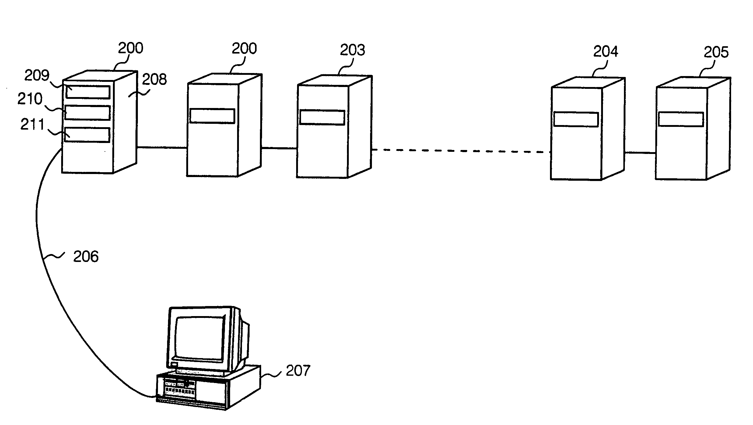
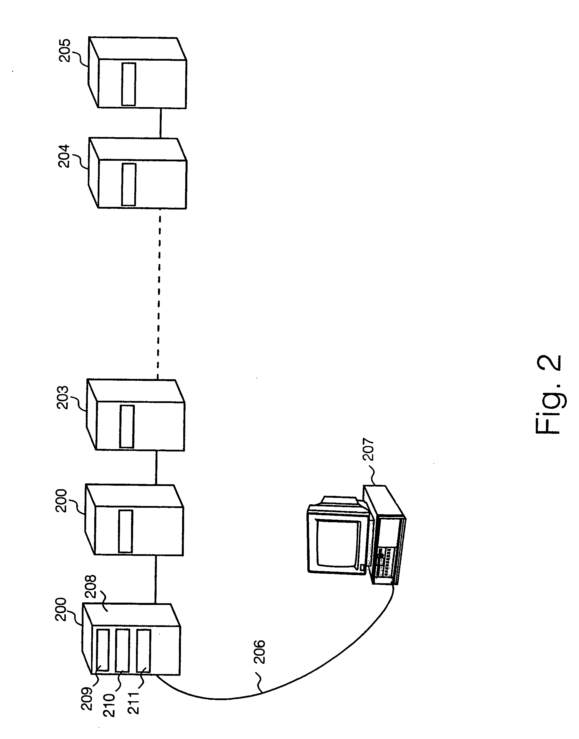
[0056] The best mode implementation is aimed at achieving scalability of computing power and data storage capacity over a plurality of headless computer entities, but without incurring the technical complexity and higher costs of prior art clustering technology. The specific implementation described herein takes an approach to scalability of connecting together a plurality of headless computer entities and logically grouping them to...


PUM


Abstract

A group of headless computer entities is formed via a local area network connection by means of an aggregation service application, operated on a headless computer entity selected as a master entity, which propagates configuration settings for time zone, application settings, security settings and the like across individual slave computer entities within the group. A human operator can change configuration settings globally at group level via a user interface display on a conventional computer having a user console, which interacts with the master headless computer entity via a web administration interface. Addition and subtraction of computer entities from a group are handled by an aggregation service application, and interlocks and error checking is applied throughout the group to ensure that no changes to a slave computer entity are made, unless those changes conform to global configuration settings enforced by the master headless computer entity.

Description

FIELD OF THE INVENTION [0001] The present invention relates to the field of computers, and particularly although not exclusively to the connection of a plurality of headless computer entities. BACKGROUND TO THE INVENTION [0002] It is know to aggregate a plurality of conventional computer entities, each comprising a processor, a memory, a data storage device, and a user console comprising a video monitor, keyboard and pointing device, e.g. mouse, to create a “cluster” in which the plurality of computer entities can be managed as a single unit, and can be viewed as a single data processing facility. In the conventional cluster arrangement, the computers are linked by high-speed data interfaces, so that the plurality of computer entities share an operating system and one or more application programs. This allows scalability of data processing capacity compared to a single computer entity. [0003] True clustering, where all the processor capacity, memory capacity and hard disk capacity a...

Claims


Application Information

Patent Timeline
Patent Type & Authority Applications(United States)
IPC IPC(8): G06F15/16G06F15/177
CPCG06F15/167H04L41/082H04L41/0893H04L41/0889H04L41/0866H04L41/0894
Inventor GOLD, STEPHENCAMBLE, PETER THOMAS
Owner HEWLETT-PACKARD ENTERPRISE DEV LP
Learn More