
Battery having specific package structure

Active Publication Date: 2005-09-01
LG ENERGY SOLUTION LTD
View PDF4 Cites 29 Cited by
  • Summary
  • Abstract
  • Description
  • Claims
  • Application Information

AI Technical Summary

Benefits of technology

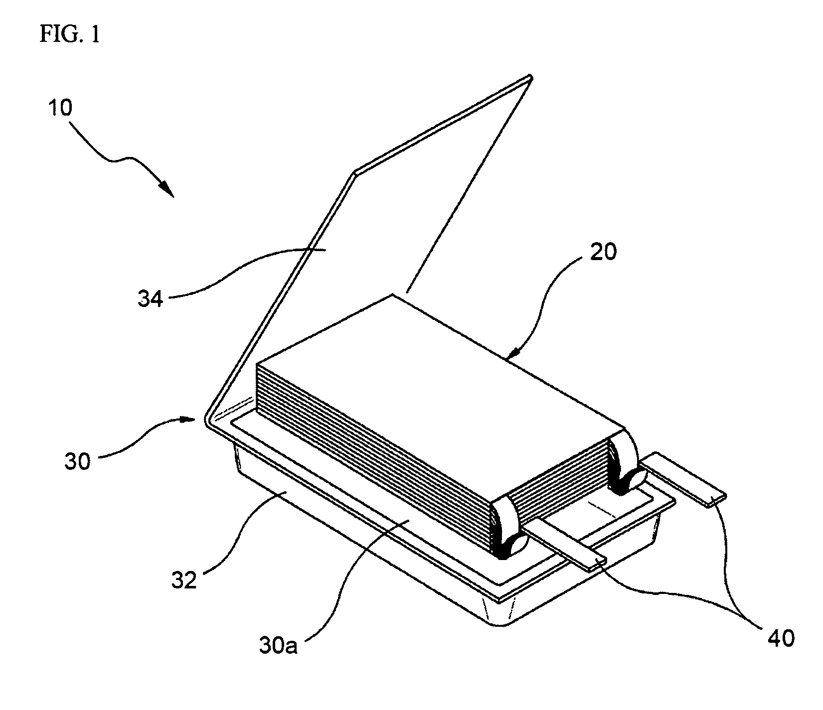
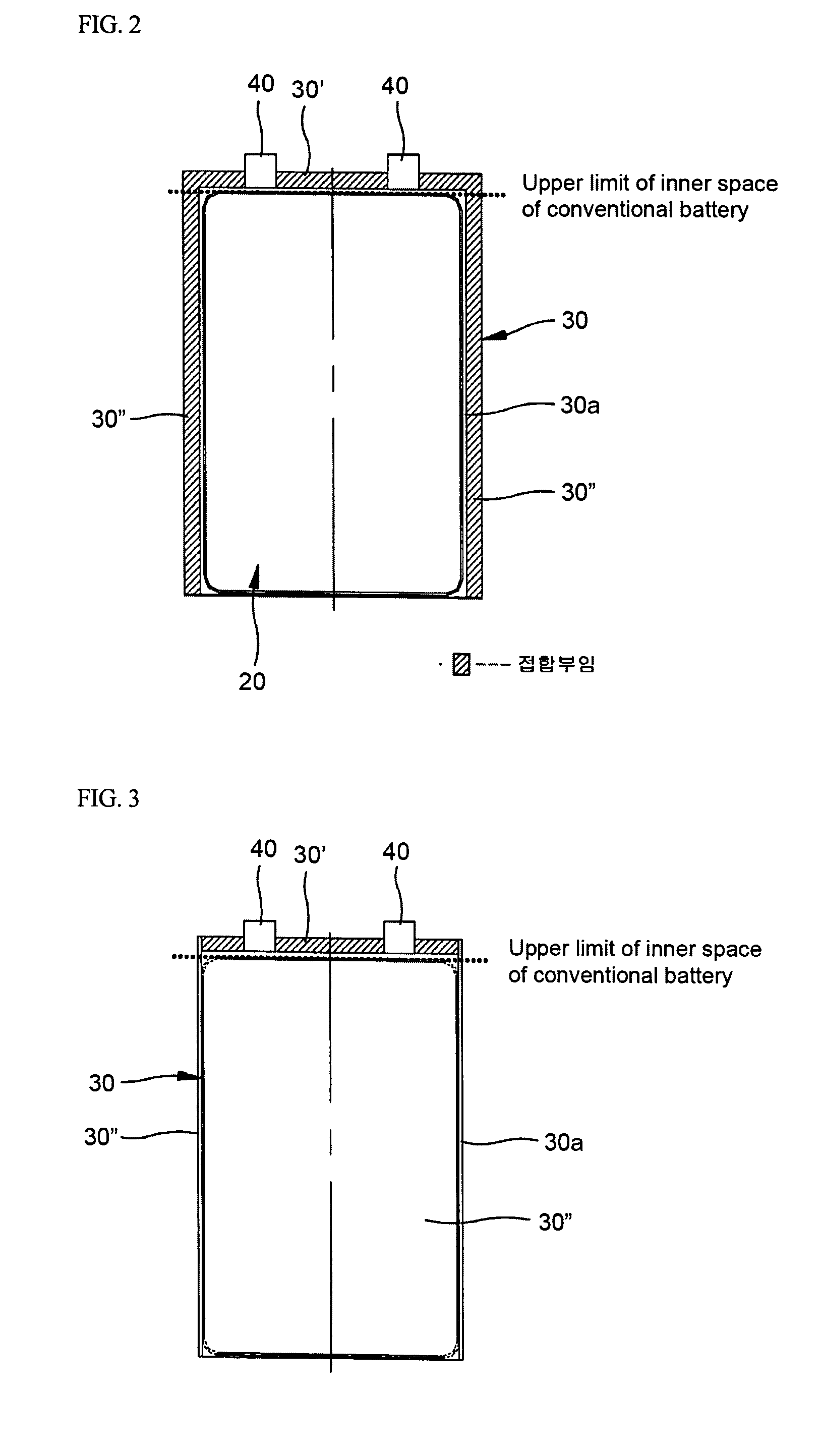
[0008] Therefore, the present invention has been made in view of the above problems, and it is an object of the present invention to provide a battery having a package structure, in which the lengths of a receipt portion of a battery case and an electrode assembly contained in the receipt portion are increased in proportion to the width occupied by an upper bonding portion of the battery case in the longitudinal direction of the battery case, thereby increasing the power storage capacity and output thereof at the same size of the battery package.
[0010] It is another object of the present invention to provide a battery having a package structure, in which, even after common portions of an upper bonding portion and both side portions of a battery case are cut off for folding the upper bonding portion toward the upper end of the battery case, the decompressed state in the battery due to vacuum is maintained by the excellent sealing capacity of the inner corners of an electrode assembly corresponding to the common portions.

Problems solved by technology

Since the length of the conventional battery having the above-described structure is limited and the upper bonding portion of the battery case of the conventional battery is extended along the longitudinal direction of the battery case, a component contained in the battery case, i.e., the electrode assembly, has a limited length, thereby decreasing the power storage capacity and the output of the battery.

Method used


Image

  • Battery having specific package structure
  • Battery having specific package structure
  • Battery having specific package structure

Examples


Embodiment Construction

[0031] Now, preferred embodiments of the present invention will be described in detail with reference to the annexed drawings.

[0032] FIGS. 6 to 10 are schematic perspective and sectional views illustrating the structure and assembly process of a battery package in accordance with one embodiment of the present invention.

[0033] Referring to FIGS. 6 to 10, the battery package 100 of this embodiment comprises an electrode assembly 200 including anode plates, cathode plates and separators, and a foldable battery case 300 hermetically sealing two electrode terminals 400 connected to corresponding electrode taps of the anode and cathode plates of the electrode assembly 200 so that the electrode terminals 400 are exposed to the outside, and including a lower body 310 and an upper body 320.

[0034] The lower body 310 includes a receipt portion 330 having a concave shape corresponding to the shape of the electrode assembly 200 for receiving the electrode assembly 200 and a designated amount ...


PUM


Abstract

The present invention provides a battery having a structure for increasing the power storage capacity and output thereof In accordance with the present invention, in a battery comprising an electrode assembly including anode plates, cathode plates and separators; and a battery case, both side bonding portions of which are folded toward adjacent sides thereof, for accommodating the electrode assembly and a designated amount of electrolyte, and sealing the electrode assembly such that two electrode terminals connected to corresponding electrode taps of the anode and cathode plates of the electrode assembly are exposed to the outside, an upper bonding portion of the battery case is folded toward the upper end of the battery case, and / or common portions of the upper bonding portion and both side portions of the battery case are cut off, and / or inner corners corresponding to the upper bonding portion have larger radiuses of curvature, and / or receipt portions for receiving the electrode assembly are respectively formed in upper and lower bodies of the battery case. The battery having the above structure has high power storage capacity and output at the same size of the battery package, and high sealing capacity and safety.

Description

BACKGROUND OF THE INVENTION [0001] The present invention relates to a battery having a package structure for increasing the power storage capacity and output thereof, and more particularly to a battery, in which an upper bonding portion is folded toward the upper end of a battery case to increase the lengths of the battery case and an electrode assembly accommodated in the battery case in proportion to the reduced width of the bonding portion in a longitudinal direction to increase the power storage capacity and output of the battery at the same size of the battery package, and preferably, in which the inner corners corresponding to the upper bonding portion have large radiuses of curvature to provide excellent sealing capacity, and more preferably, in which upper and lower bodies of the battery case are separated from each other and receipt portions for receiving the electrode assembly are respectively formed in the upper and lower bodies to further improve the power storage capaci...

Claims


Application Information

Patent Timeline
IPC IPC(8): H01M10/04H01M10/05H01M10/0585H01M10/0587H01M10/38H01M10/42H01M50/55H01M50/553
CPCH01M2/021H01M10/425H01M10/058H01M10/04Y02E60/10Y02P70/50H01M50/553H01M50/55
Inventor KANG, HEE GYOUNGLEE, HYANG MOKHYUN, OH YOUNGAHN, CHANG BUMHWANG, SUNG-MIN
Owner LG ENERGY SOLUTION LTD
Learn More