
Method and system for containment, such as a containment cap for solid waste constructed of modified asphalt

a technology of containment and solid waste, which is applied in the field of containment and environmental applications, can solve the problems of high volume reduction, ineffective barrier layer composed of clay and geomembrane under subtitle c, and high cost and construction difficulty, and achieves the effects of reducing cost, reducing volume, and reducing volum

Inactive Publication Date: 2005-09-01
MATCON
View PDF5 Cites 10 Cited by
  • Summary
  • Abstract
  • Description
  • Claims
  • Application Information

AI Technical Summary

Benefits of technology

[0013] The present invention advantageously provides a system of containment that is cost-effective, meets stringent EPA standards, is resistant to erosion, remains stable on slopes and conforms to settlement, is resilient over a wide range of temperature variations and is not subject to damage under UV light exposure, offers longevity, ease of maintenance and inspection, provides a thinner cross-section requiring less material import and more storage space, rapid installation with conventional construction equipment, and allows reuse of the site or a variety of potential alternative uses: parking, equipment storage, truck / train intermodal facilities, multi-use sports facilities, and the like.

Problems solved by technology

However, most landfills in the U.S. do implement the soil covers and compacted clay cover designs of subtitles D and C, often with little regard for regional conditions.
These designs are used even though the EPA has found that a barrier layer composed of clay and a geomembrane under subtitle C is “not very effective” in arid regions.
As the soil dries, it experiences a high level of volume reduction, which leads to cracking caused by shrinkage.
The EPA guidelines state: “this traditional cover not only is inherently problematic, but is also very expensive and difficult to construct.
Furthermore, the basic soil cover used with Subtitle D also has its problems, as the barrier layer is subject to deterioration due to freeze / thaw cycles.”
Installations of these systems are costly due to the multi-layer design.
These systems were historically subject to damage during construction from equipment, and thereafter from vegetation roots and small animals.
Further limitations of the multi-layer membrane systems included difficulty visually inspecting the buried membrane.
Rupture of the membrane during installation or thereafter would render the system useless for its intended purpose.
Not only was detection of a leak difficult, but repair required excavation of the various layers and risked further damage upon re-exposing the membrane layers.
Often due to the nature of the membranes, the site was no longer available for future use as a storage facility or other use due to restrictions on loading.
Other construction materials were historically not sufficiently impermeable or resilient to be used in place of the geosynthetic or membrane.
Further, conventional asphalt is typically sensitive to temperature changes.
A 1988 study by the EPA of randomly selected landfills revealed that the vast majority are leaking, and many have caused severe contamination of the groundwater and surrounding ecosystems.

Method used


Image

  • Method and system for containment, such as a containment cap for solid waste constructed of modified asphalt
  • Method and system for containment, such as a containment cap for solid waste constructed of modified asphalt
  • Method and system for containment, such as a containment cap for solid waste constructed of modified asphalt

Examples


Embodiment Construction

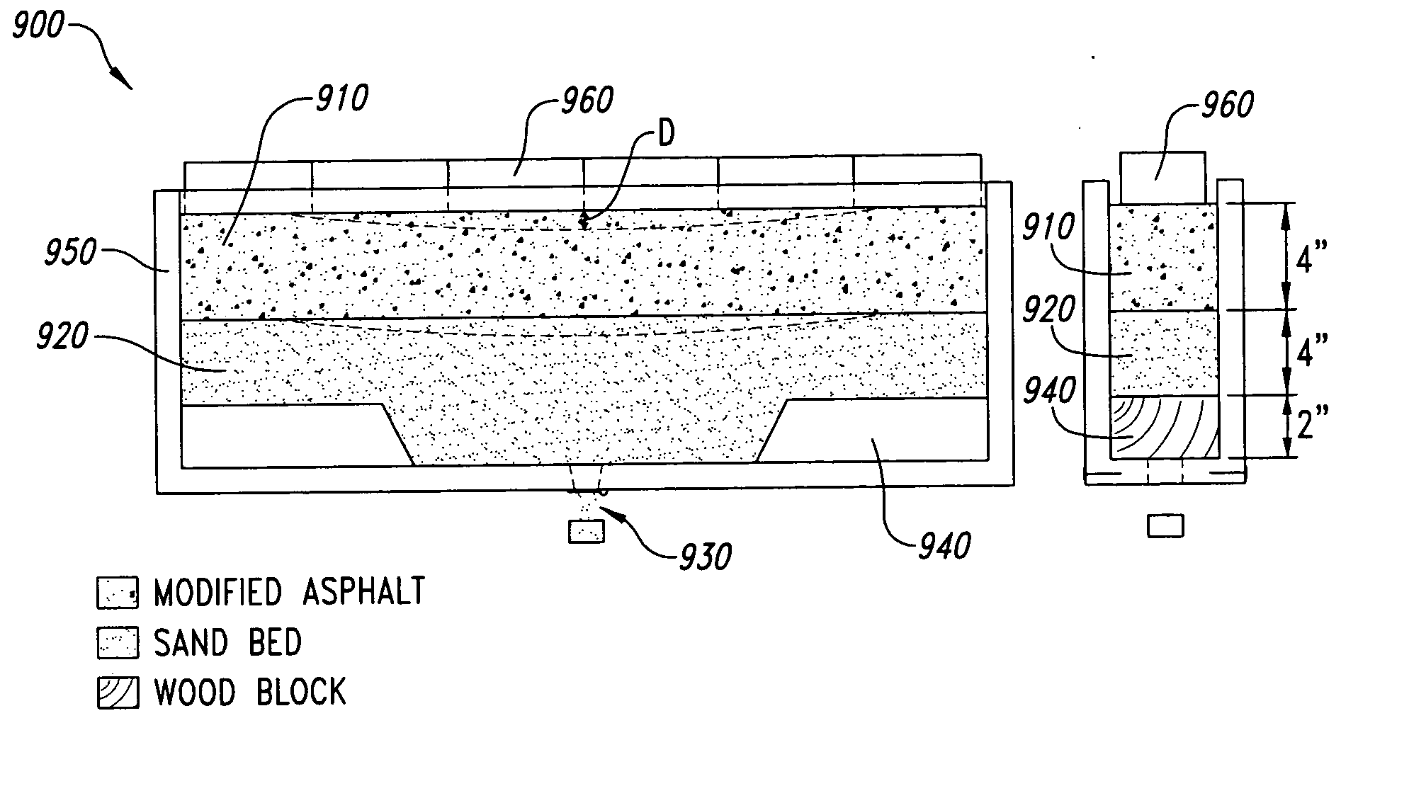
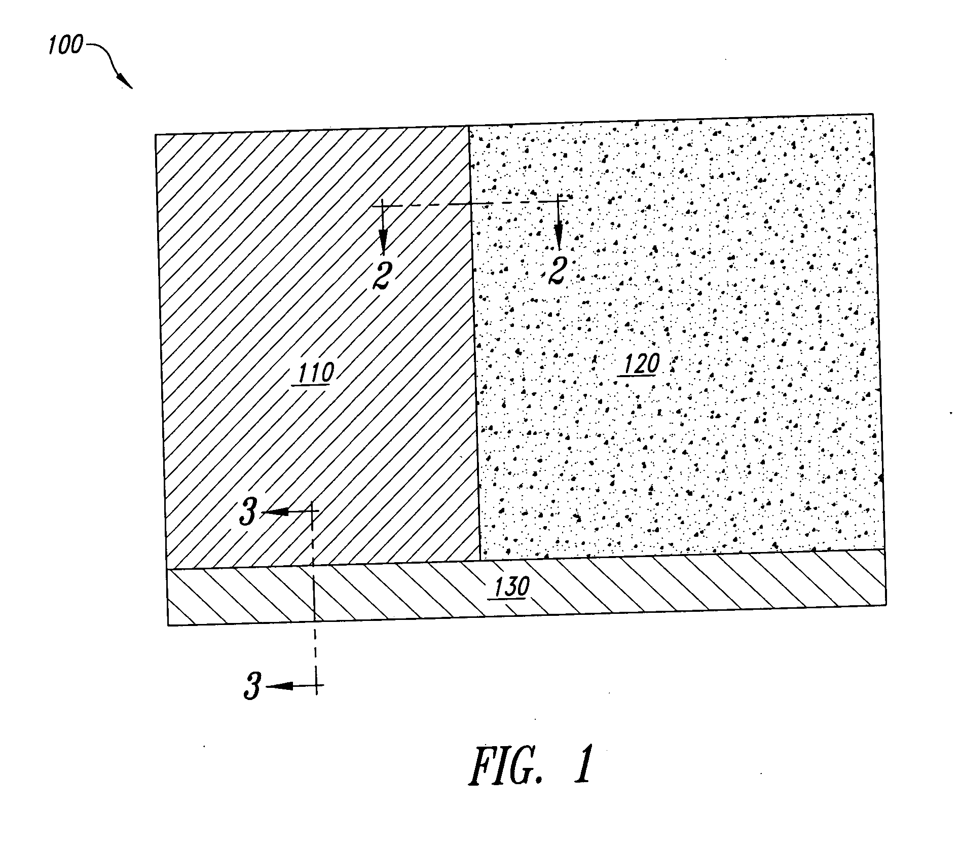
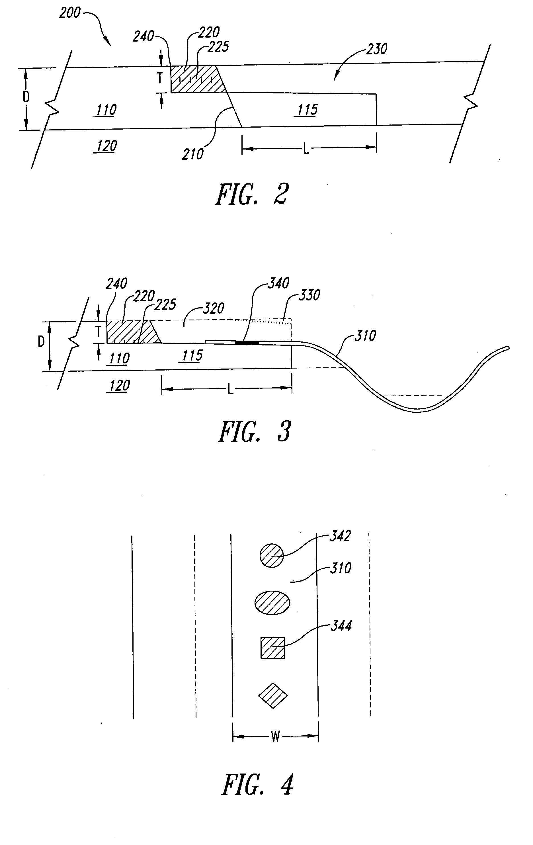
[0030] The present invention is directed to a waste or environmental containment system to contain hazardous wastes at RCRA and Superfund sites, landfills, brownfields, spills and industrial sites. The system includes modified asphalt specifically designed for containment, and a system of installation that provides a seamless cap over the area to be contained. The modified asphalt contains high quality, specifically sized mineral aggregate and a highly modified binder using additives beneficial to environmental applications. Under aspects of the invention, the specifically designed modified asphalt mixture has a permeability coefficient less than 1×10⁻⁷ cm / sec and an air void content less than 3 percent. Under another aspect of the invention, cold and hot joint designs provide a seamless containment cap.

[0031] The modified asphalt of the present invention has met EPA guidelines for use in waste containment applications. The permeabilities, flexural properties, load capacity, tensil...


PUM


Abstract

The present invention is directed to a waste or environmental containment system that includes modified asphalt specifically designed for containment, and a system of installation that provides a seamless cap over the area to be contained. The modified asphalt of the present invention has a permeability less than 1×10⁻⁸ cm / sec and an air void content less than 3 percent. The system of installation includes joint designs that meet the same parameters as the modified asphalt mat to provide a seamless containment cap or liner to contain hazardous wastes at RCRA, Superfund sites, waste sites and environmental containment areas.

Description

BACKGROUND OF THE INVENTION [0001] 1. Field of the Invention [0002] This invention relates to a method and system for waste containment and environmental applications, and more particularly, to a cap or liner system constructed of a modified asphalt mixture for use in a waste and environmental containment system. [0003] 2. Description of the Related Art [0004] When municipal solid waste and waste and hazardous waste landfills reach their capacities, the waste sites are capped with a final cover that keeps out rainfall and prevents leachate generation and possible environmental contamination. These final covers have traditionally been constructed of layers of clay, sand, vegetated topsoil and, sometimes, geosynthetic materials. Additional sites that require cover include brownfields, spills and industrial sites. [0005] The U.S. Environmental Protection Agency (EPA) has strict regulations for these waste containment and environmental cleanup sites. The EPA has developed a standard of ...

Claims


Application Information

Patent Timeline
IPC IPC(8): E02D31/00
CPCE02D31/004B09B1/004Y02W30/30
Inventor TERREL, RONALD L.YOST, KARLSCHWIESOW, GALE
Owner MATCON
Learn More