Lens meter

a technology of lens meter and meter, which is applied in the direction of measuring devices, instruments, structural/machine measurement, etc., can solve the problems of not easily available and expensive, measurement target images that cannot be referenced by diopters, and short measurement target images, etc., to achieve the effect of easily and efficiently measuring even progressive lenses and the lik

Inactive Publication Date: 2005-09-01
NIDEK CO LTD
View PDF12 Cites 16 Cited by
  • Summary
  • Abstract
  • Description
  • Claims
  • Application Information

AI Technical Summary

Benefits of technology

[0007] An object of the invention is to overcome the problems described above and to provide a lens meter capable of obtaining coordinates with a “0D reference” of even measurement target images not detected by a photo-sensor in a reference state where a lens is not placed on a measurement optical axis, and measuring even a progressive lens and the like easily and efficiently.

Problems solved by technology

Besides, in the conventional lens meter, the measurement targets are arranged limitedly within a range narrower than a photo-receiving surface of the photo-sensor.
Therefore, when a portion which is not in the vicinity of an optical center of the lens such as an add section of a progressive lens or a bifocal lens is measured, there is a case where a part of the measurement target images is not detected due to generation of prism power (diopter), so that the measurement target images necessary for measurement come to short.
Although there is a photo-sensor with a large photo-receiving surface, it is not easily available and is expensive.
When the measurement targets are arranged in a range wider than the photo-receiving surface of the photo-sensor in order to cope with the problems as above, some measurement target images are inevitably not detected in the reference state, and coordinates with so-called a “0D (diopter) reference” cannot be obtained for those measurement target images.

Method used


Image

  • Lens meter
  • Lens meter
  • Lens meter

Examples


Embodiment Construction

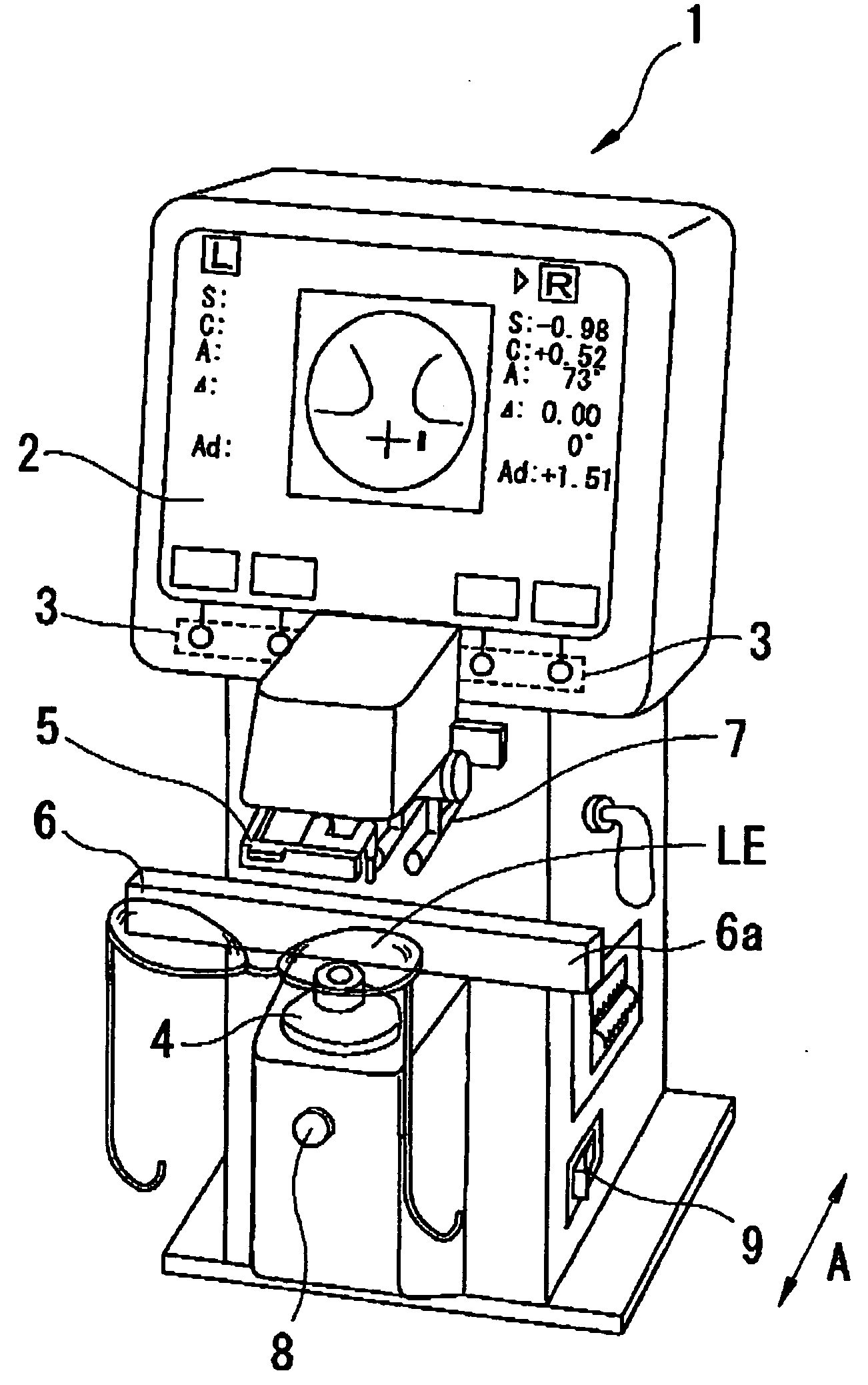
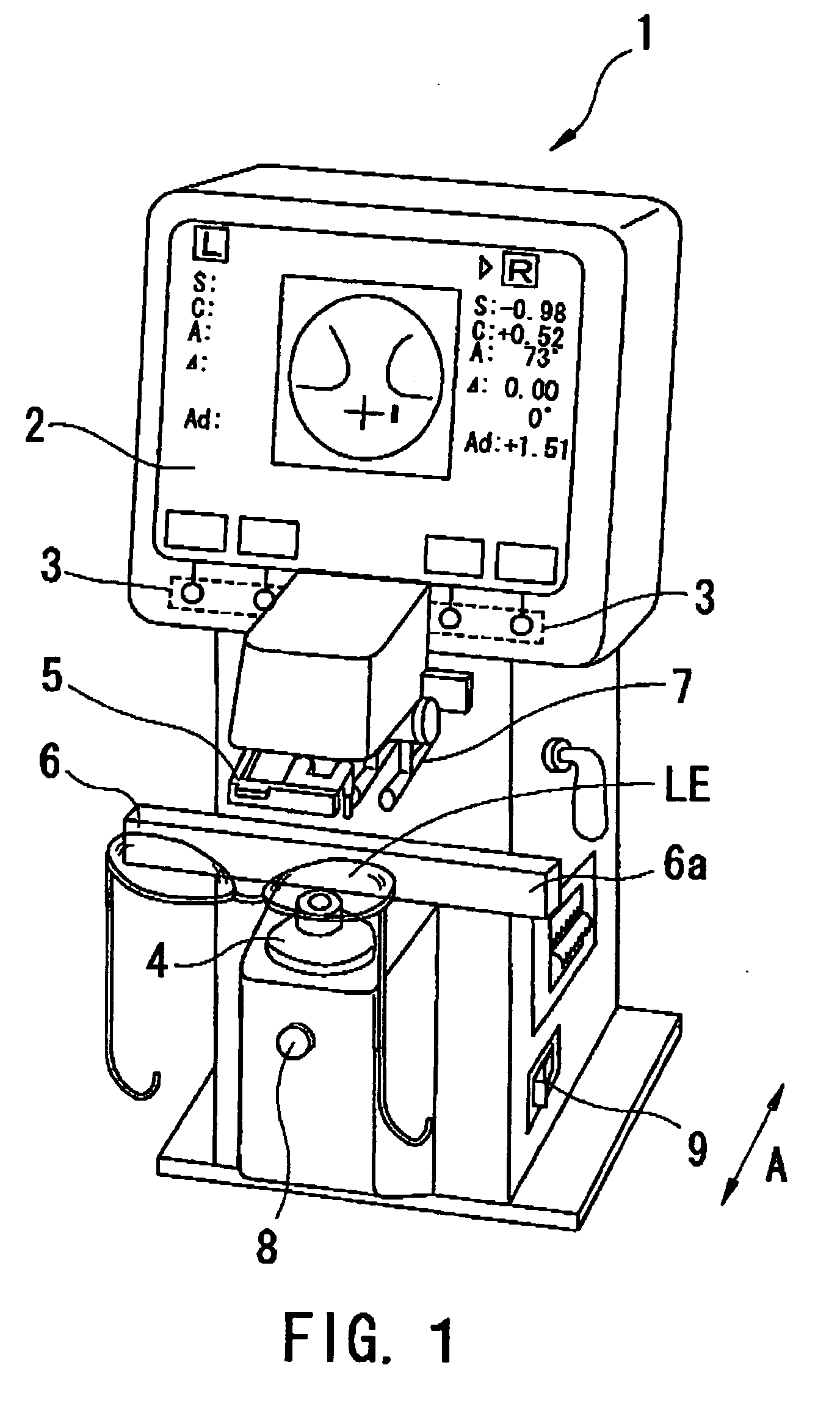
[0016] A detailed description of one preferred embodiment of a lens meter embodied by the present invention is provided below with reference to the accompanying drawings. FIG. 1 is a view showing a schematic external view of a lens meter consistent with the preferred embodiment of the present invention.

[0017] On a display 2 such as a liquid crystal display arranged on the top of a body 1 of the lens meter, information necessary for measurement such as a mark for alignment, measurement results, and the like are displayed. Further, at the press of one of switches 3 corresponding to switch displays on the display 2, necessary instructions such as measurement mode switching are inputted.

[0018] A lens LE to be measured is mounted on a nosepiece (lens rest) 4, and a lens holder 5 is moved downward (to a nosepiece 4 side) to stably hold the lens LE mounted on the nosepiece 4.

[0019] When measuring the lens LE in frames, a frame table (lens table) 6 is brought into contact with the lower ...


PUM


Abstract

A lens meter obtaining 0D-reference-coordinates of target-images not detected in a reference state and measuring even progressive lenses, has a lens rest, an optical system having an optical axis, a light source, measurement targets and a photo-sensor, a part calculating optical characteristics based on coordinates-change of target-images in a measurement state with the lens on the rest and axis from those in a reference state without the lens thereon, and an information memory. The part makes the memory store image-coordinates not detected in the reference state obtained during assembly / adjustment, and based on image-coordinates detected in the reference state after power application and before measurement and stored coordinates, obtains image-coordinates not detected in the reference state after power application and before measurement, and calculates characteristics based on coordinates-change of target-images detected in the measurement state from those detected in the reference state before measurement and obtained image-coordinates.

Description

SUMMARY OF THE INVENTION [0001] 1. Field of the Invention [0002] The present invention relates to a lens meter for measuring optical characteristics of a lens for an eye such as a spectacle lens. [0003] 2. Description of Related Art [0004] Conventionally, there is known a lens meter which places a lens on a measurement optical axis, projects a measurement light bundle onto the lens and measurement targets and photo-receives the measurement light bundle passed through the lens and the measurement targets by using a photo-sensor, and then obtains optical characteristics of the lens based on the photo-receiving results. This kind of lens meter previously obtains coordinates (positions) of images of the measurement targets detected by the photo-sensor in a reference state where the lens is not placed on the measurement optical axis (a lens-absent state), then obtains coordinates (positions) of images of the measurement targets detected by the photo-sensor in a measurement state where th...

Claims


Application Information

Patent Timeline
Patent Type & Authority Applications(United States)
IPC IPC(8): G01M11/02
CPCG01M11/0207G01M11/0235G01M11/0228G01M11/0214G01M11/02
Inventor KAJINO, TADASHI
Owner NIDEK CO LTD
Why Eureka
Try Eureka