
Media discharging unit for media dispenser

a technology of media dispensers and discharging units, which is applied in the direction of pile separation, transportation and packaging, instruments, etc., can solve the problems of difficult removal, difficult repair, and difficulty in removing related art, and achieve the effect of easy access to the components provided therein

Active Publication Date: 2005-09-01
ATEC AP CO LTD
View PDF26 Cites 36 Cited by
  • Summary
  • Abstract
  • Description
  • Claims
  • Application Information

AI Technical Summary

Benefits of technology

[0013] Therefore, the present invention is conceived to solve one or more of the aforementioned drawbacks in the related art. An object of the present invention is to provide a media discharging unit for a media dispenser wherein access to the components provided therein is easy.
[0014] Another object of the present invention is to provide a media discharging unit for a media dispenser wherein a position for feeding media to a customer can be set freely.
[0015] A further object of the present invention is to make delivered media compact when several sheets of the media are provided to a customer.
[0017] A still further object of the present invention is to improve an operational reliability for feeding multiple sheets of media at a time.
[0018] A still further object of the present invention is to provide a media discharging unit for a media dispenser, which can precisely sense the thickness of media and be used for various media.

Problems solved by technology

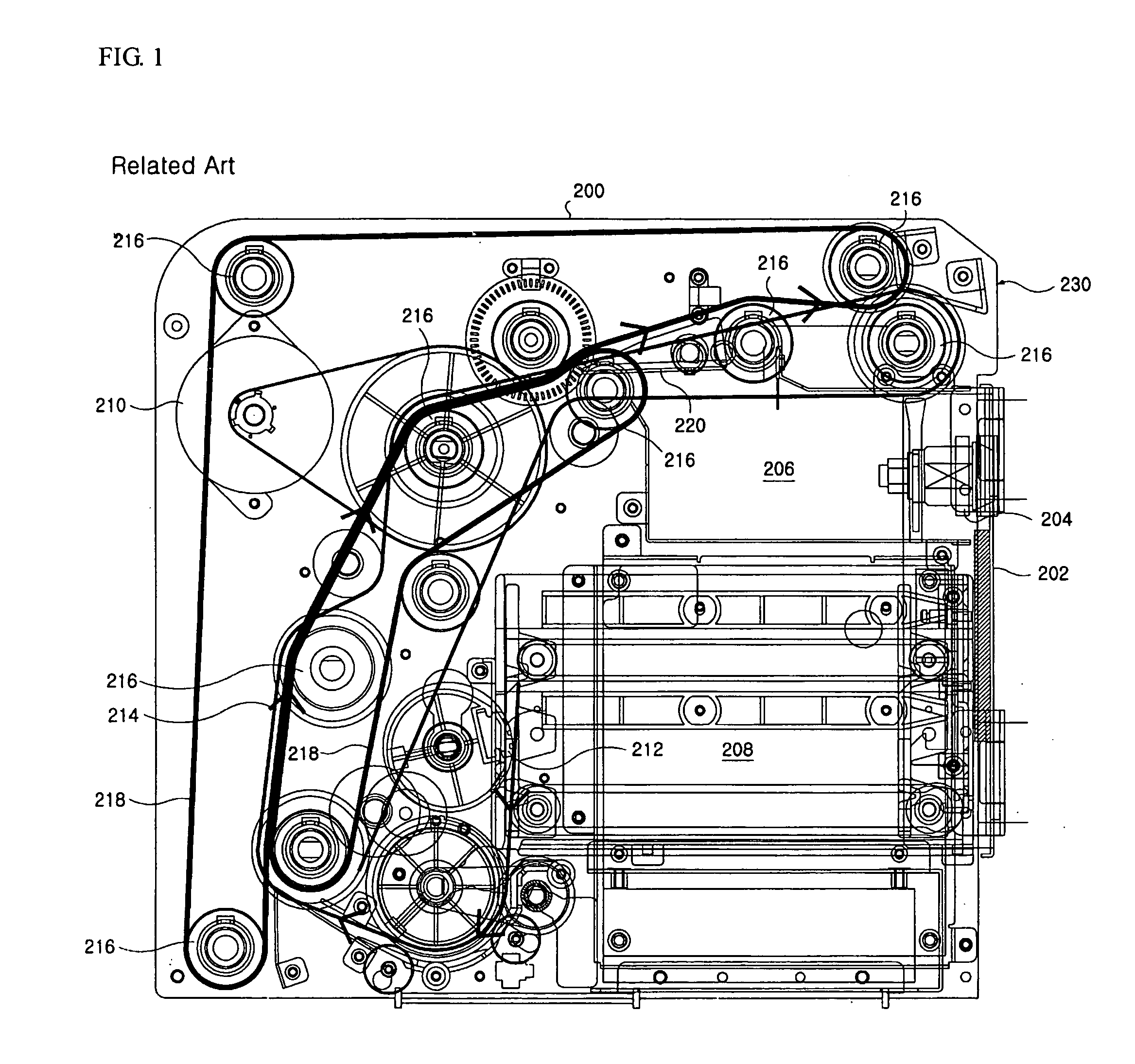
However, such a related art has some drawbacks.
Therefore, if the media are jammed on the feeding path 214, it is very difficult to remove them.
In particular, if the components forming the feeding path 214, especially those components between the guide plates 200, are damaged, it is very difficult to repair them.
Furthermore, since the constructions of the related art is so designed that the discharge part 230 is provided in a side of the guide plates 200, it is a drawback that the entire construction provided in the guide plates 200 would have to be redesigned in order to change the direction of the discharge part.
Thus, sheets of the media are not closely stacked and become large in volume, so that it is very inconvenient for the customer taking them by hand.
Thus, that is also a drawback since there is no way to retrieve the media, once provided to the customer, into the media dispenser if the customer fails to take the dispensed media.

Method used


Image

  • Media discharging unit for media dispenser
  • Media discharging unit for media dispenser
  • Media discharging unit for media dispenser

Examples


Embodiment Construction

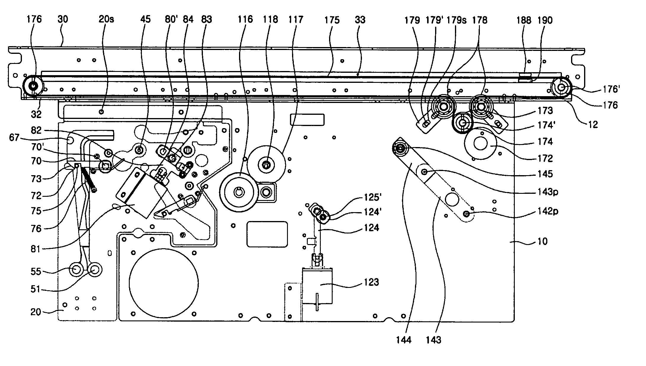
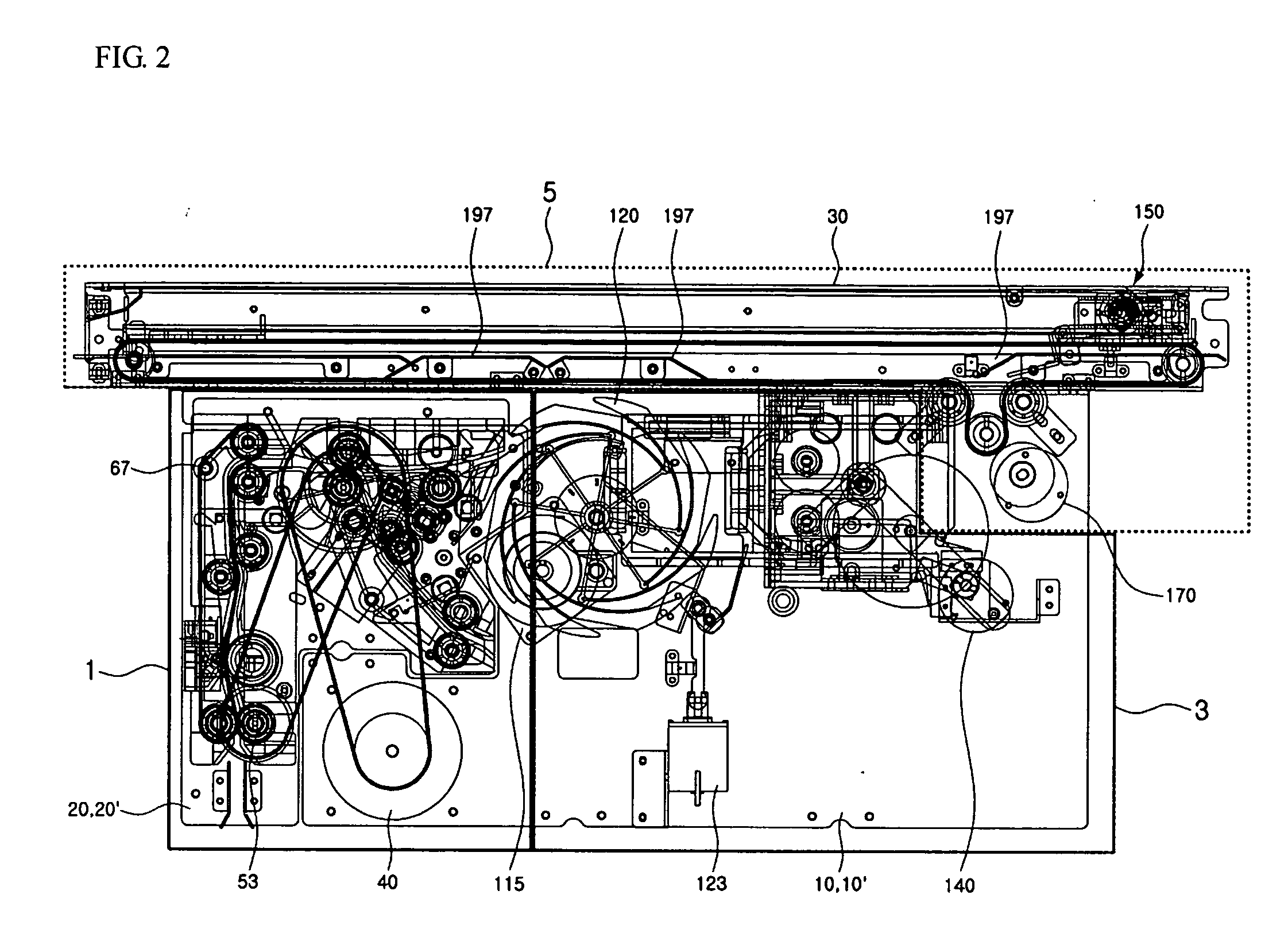
[0072] Referring to the accompanying drawings, a preferred embodiment of a media discharging unit for a media dispenser according to the present invention will be explained. FIG. 2 shows an entire construction of the embodiment of the present invention, wherein the present invention generally comprises a delivery module 1, a stacking module 3 and a stack delivery module 5. The delivery module 1 functions to separate sheets of media from a media box (not shown), in which the media are stored, one-by-one and feed them to a predetermined position. Upon feeding the media, the delivery module 1 also functions to separate the rejectable media from the dischargeable media by sensing the thickness of the media.

[0073] The stacking module 3 functions to collect desired sheets of the media fed from the delivery module 1 and then feed them in stack form to the stack delivery module 5. The stack delivery module 5 functions to feed the media fed from the stacking module 3 to a position where a c...


PUM

PropertyMeasurementUnit
Thicknessaaaaaaaaaa
Forceaaaaaaaaaa
Angleaaaaaaaaaa

Abstract

The present invention relates to media discharging unit for a media dispenser. The present invention includes a delivery module, which selectively feeds media fed from a media box to a discharge position and a reject position one-by-one using belts and rollers. A stacking module is separable from the delivery module, and collects the media, which are fed by the delivery module, one-by-one upon the rotation of a stacking wheel and then feeds the collected media as a stack at one time. A stack delivery module is separable from the stacking module, and clamps the stacked media, which are collected in the stacking module, and feeds the stacked media to a position where a customer can take the media.

Description

[0001] This application claims the priority benefit of Patent Application No. 2003-10-098249 filed on Dec. 27, 2003 in Korea, which is hereby incorporated by reference. BACKGROUND OF THE INVENTION [0002] 1. Field of Invention [0003] The present invention relates to a media dispenser, and more particularly, to a media discharging unit for a media dispenser to take out a customer's desired number of media from a media box and to feed them to the customer. [0004] 2. Description of the Prior Art [0005]FIG. 1 shows the construction of a related art media dispenser. According to the figure, various components for feeding media are provided between two guide plates 200 with a predetermined spacing. The front surface of the media dispenser corresponding to an end of the guide plates 200 is provided with a door 202 for selectively opening or closing a predetermined space formed between the guide plates 200. The door 202 is installed at a side of the guide plates 200 so as to be opened or clo...

Claims


Application Information

Patent Timeline
IPC IPC(8): G07F19/00B65H31/30G07D11/00
CPCB65H2301/42146B65H2301/42242B65H31/3045G07D11/0018B65H2701/1912G07D11/14G07F19/00
Inventor KO, KYUNG-HO
Owner ATEC AP CO LTD
Learn More