
Blood pressure monitor

a blood pressure monitor and monitor technology, applied in the field of blood pressure monitors, can solve the problems of inconvenient and labor-intensive blood pressure monitors, large resistance, and difficulty in adjusting the cuff, and achieve the effect of suppressing the consumption of electric power

Active Publication Date: 2005-08-25
MATSUSHITA ELECTRIC WORKS LTD
View PDF9 Cites 30 Cited by
  • Summary
  • Abstract
  • Description
  • Claims
  • Application Information

AI Technical Summary

Benefits of technology

[0008] Another object of the present invention is to provide a blood pressure monitor which can evenly press an arm or the like of a measurer.
[0009] Still another object of the present invention is to prevent an epidermis part of an arm from getting in a cuff.
[0010] Further another object of the present invention is to provide a blood pressure monitor which can suppress the consumption of an electric power.
[0011] Still another object of the present invention is to provide a blood pressure monitor which can constantly measure a blood pressure at a fixed measuring position.
[0013] Preferably, the blood pressure monitor may be provided with at least one of a fastening force adjusting construction for adjusting a force of the cuff to evenly fasten the arm or the like of the measurer, a construction for preventing the epidermis part of the arm from getting in the cuff, a construction for suppressing the consumption of an electric power, and a construction for fixing a measuring position.

Problems solved by technology

Specifically, there have been the following problems.
However, with the blood pressure monitor having the automatic take-up mechanism, the epidermis part of the arm may be pulled by the cuff being taken up and may get in between lateral portions of the arm rest and the cuff when the cuff is taken up by the automatic take-up mechanism.
The blood pressure monitor of the hand winding type has a problem of being inconvenient and taking much labor because the cuff is hand-wound.
However, there is a large resistance at the time of taking up and rewinding the cuff.
Further, it is difficult to know how much an arm should be inserted when a measurer inserts his arm.
If the arm is inserted too deeply or too lightly, there is a problem of being unable to make a precise measurement.

Method used


Image

  • Blood pressure monitor
  • Blood pressure monitor
  • Blood pressure monitor

Examples


Embodiment Construction

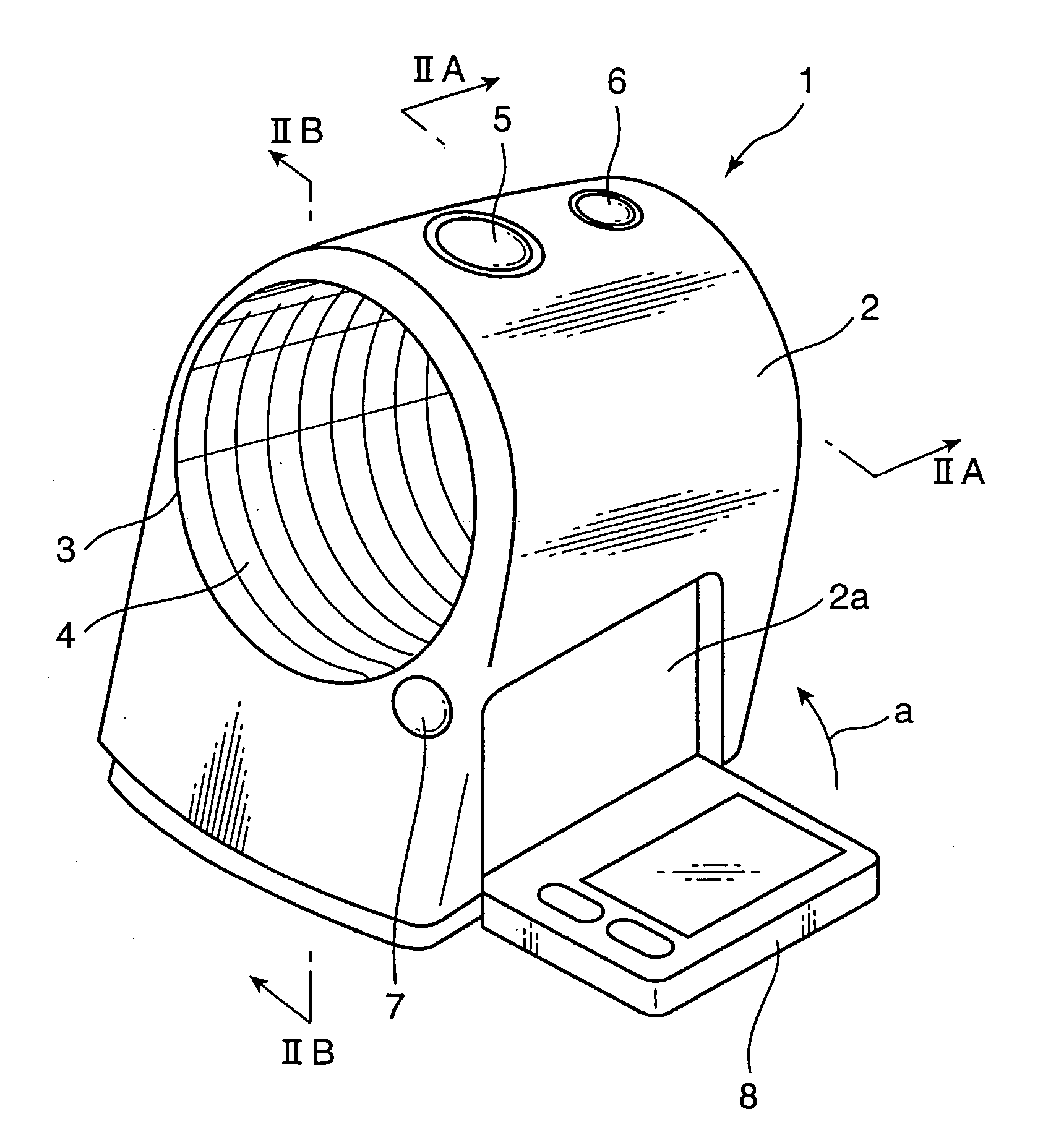
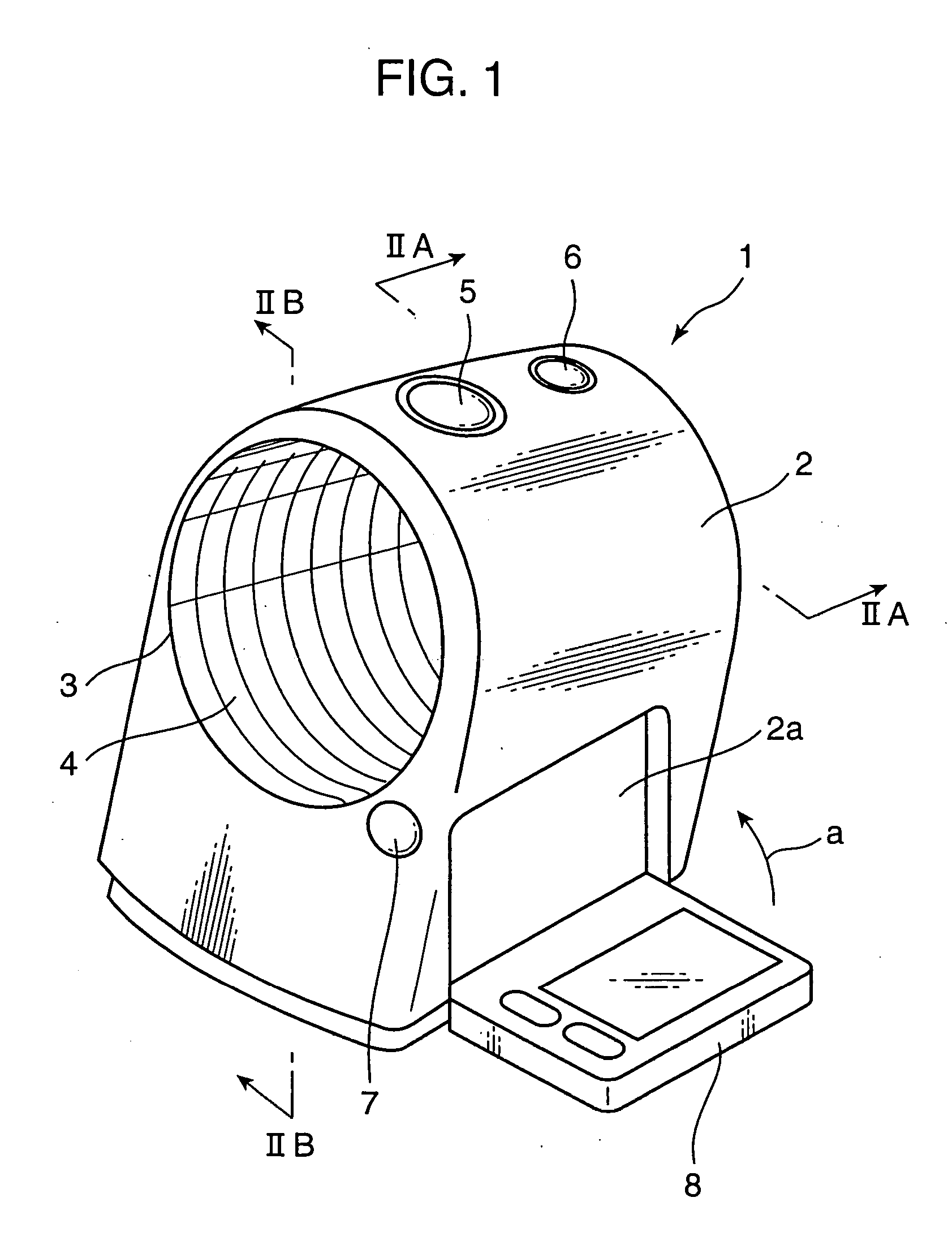
[0066] A blood pressure monitor according to an embodiment of the present invention is shown in FIG. 1. This blood pressure monitor 1 has a compact and simple construction for home use, wherein a box-shaped housing 2 is formed with an arm inserting hole 3 penetrating the housing 2 along forward and backward directions and a soft tubular cuff ring 4 into which an arm is inserted is arranged in the arm inserting hole 3. The cuff ring 4 is made of a fabric of a polyethylene or the like.

[0067] A start / end switch 5 and an emergent exhaust switch 6 are provided at the top of the housing 2, an opening button 7 for opening a display panel 8 is provided at the front side, and the display panel 8 openable and closable by a hinge is provided at a side. Upon being closed in a direction of arrow “a” from an open position shown in FIG. 1, the display panel 8 is accommodated and locked at a closed position by being fitted into a recess 2a formed in a side surface of the housing 2. When the openin...


PUM


Abstract

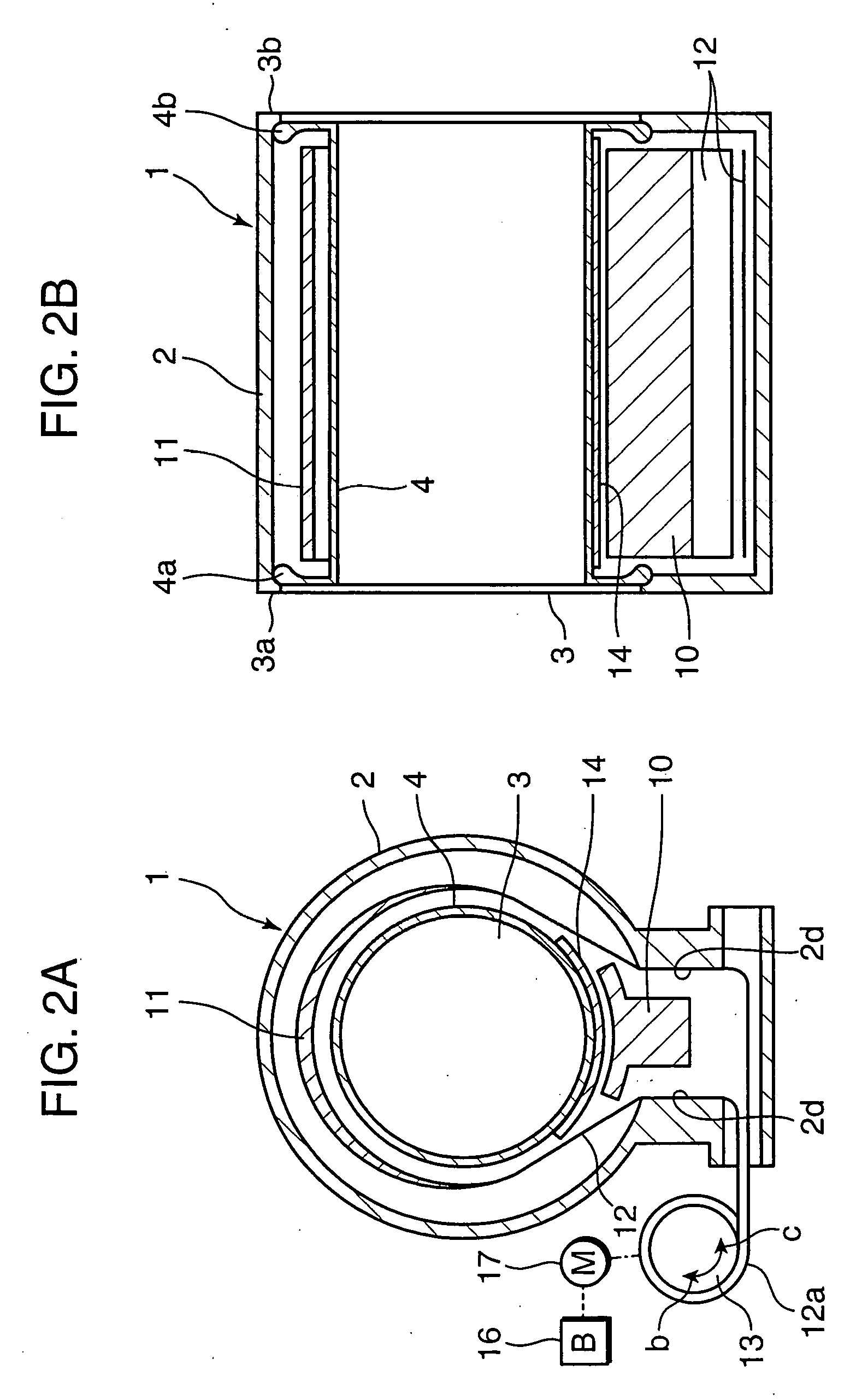
A blood pressure monitor is provided with a box-shaped housing having openings formed in left and right side walls, a cuff transversely arranged in the housing and including an arm entrance and an arm exit at the opposite left and right ends corresponding to the openings. The cuff is formed with a blood flow blocking bag in a specified area. The opposite ends of the cuff is taken up by a cuff take-up drum such that the blood flow blocking bag extends along the outer circumferential surface of the inserted arm at the time of a measurement and a compressed air is supplied to the blood flow blocking bag to block the blood flow. The blood pressure monitor is further provided with at least one of a fastening force adjusting construction for adjusting a force of the cuff to evenly fasten the arm or the like of the measurer, a construction for preventing the epidermis part of the arm from getting in the cuff, a construction for suppressing the consumption of an electric power, and a construction for fixing a measuring position.

Description

BACKGROUND OF THE INVENTION [0001] The present invention relates to a blood pressure monitor for measuring a blood pressure using an arm. BACKGROUND OF THE INVENTION [0002] For the measurement of a blood pressure, it has been a conventional practice to insert an arm of a measurer into an arm insertion hole formed by a cuff holding a blood flow blocking bag, then to fix the cuff to the arm, and to measure a blood pressure by inflating the blood flow blocking bag to apply a specified pressure (for example, Japanese Unexamined Patent Publication No. H01-254146, Japanese Patent No. 3235602). However, there have been recognized main points to be improved, for example, in order (1) to enable a precise measurement, (2) not to give any feeling of pressure or any feeling of tension of a measurement to a measurer, and (3) to enable an efficient use of a driving energy of a blood pressure monitor. Specifically, there have been the following problems. [0003] An arm to be measured, normally an u...

Claims


Application Information

Patent Timeline
IPC IPC(8): A61B5/022
CPCA61B5/02233A61B5/022
Inventor FUMURO, SHINICHIOKADA, KOICHIKOJIMA, TAKESHIYUASA, TSUYOSHIIWAI, NOBUO
Owner MATSUSHITA ELECTRIC WORKS LTD
Learn More