
Dental pliers

Inactive Publication Date: 2005-08-25
INTEGRA YORK PA
View PDF13 Cites 24 Cited by
  • Summary
  • Abstract
  • Description
  • Claims
  • Application Information

AI Technical Summary

Benefits of technology

[0005] The invention is concerned with the task of providing dental pliers which are easy to assemble and to again reassemble.
[0011] Further a friction element can be provided between the surfaces of the journal and the bore which are in contact with each other. This friction element has the function of imparting a defined resistance or friction in the pivot movement of the pliers. By the selection of the material and the dimensions of the friction element or insert, a defined predetermined resistance can be produced, so that the pliers on the one hand are sufficiently easily to operate and on the other hand do not move unintentionally out of the respective pivot position. If the bore is a blind bore, then the friction insert or element is preferably in the form of a disc inserted between the base of the bore and the axial surface of the journal. Thereby an even friction effect in any rotation position and an even friction or wear of the friction insert is guaranteed.
[0014] Thereby there results overall a savings in material and manufacturing costs. Besides this, it is possible to combine pliers jaws and pliers lever arms with each other in diverse manner, so that a large variety of types of pliers can be produced without requiring for each type its individual manufacturing from a blank.

Problems solved by technology

The disassembly of the pliers is however laborious and time consuming.

Method used


Image

  • Dental pliers
  • Dental pliers
  • Dental pliers

Examples


Embodiment Construction

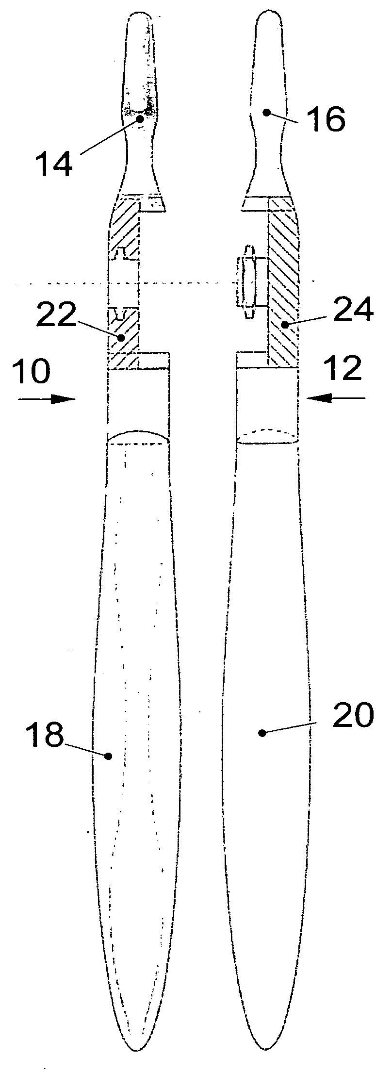
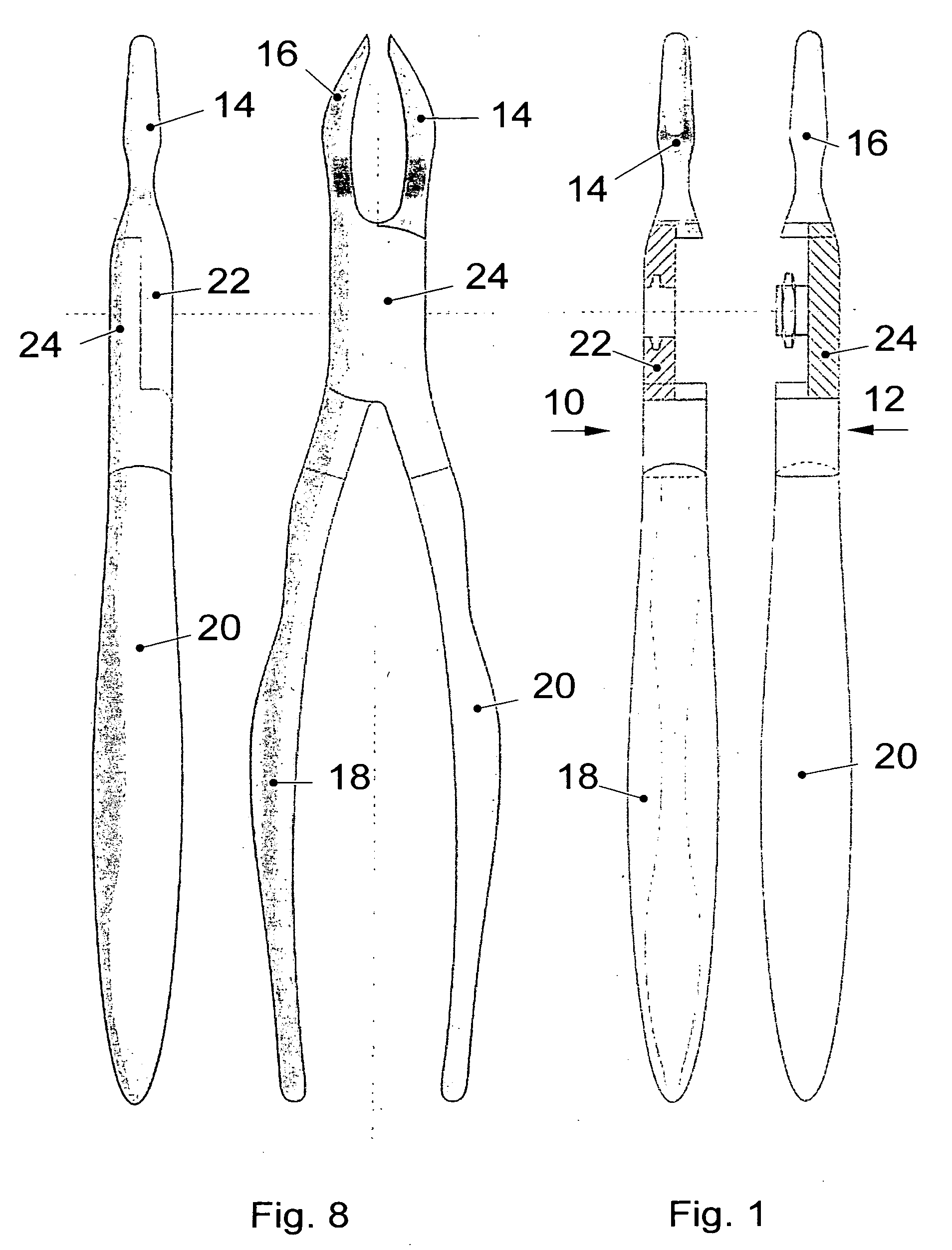
[0027] The pliers, which in the illustrative embodiment are shown as dental extraction pliers, are comprised of two pliers parts 10 and 11. The two pliers parts 10 and 11 are comprised in known manner respectively of a jaws 14 or as the case may be 16, a lever arm 18 or as the case may be 20 and a linkage area 22 or as the case may be 24, which connects the respective jaw 14 or as the case may be 16 with the respective lever arm 18 or as the case may be 20. The jaws 14 and 16 form the pliers mouth and have a design which depends upon the respective intended use of the pliers. The lever arms 18 and 20 form the pliers grip and are likewise adapted to the corresponding respective intended use of the pliers.

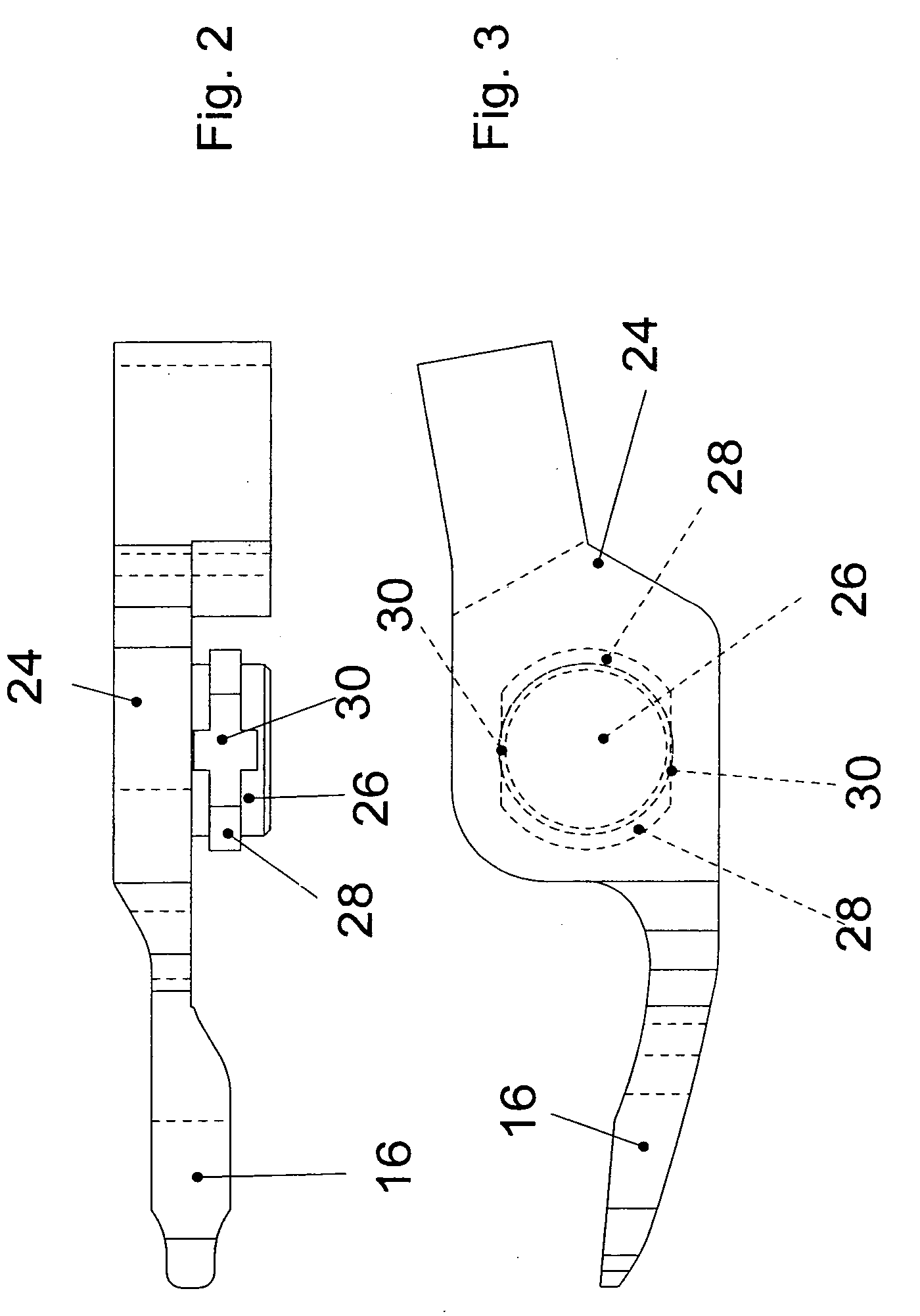
[0028] The two pliers parts 10 and 12 are pivotably linked with each other via a linkage, which will be explained in greater detail in the following on the basis of FIGS. 2 through 7. In the illustrative embodiment the purpose of the linkage formed as inserted linkage, in which the ...


PUM


Abstract

Dental pliers with two pliers parts, each respectively comprising one jaw of a pliers mouth and one lever arm of a pliers grip, the pliers parts pivotably connected with each other via a linkage. The linkage includes a cylindrical journal (26) on the first pliers part (12) coaxial to the pivot axis, which engages in a cylindrical bore (32) on the other pliers part (10) coaxial to the pivot axis having the same diameter, and is rotatable in this bore (32) about the pivot axis. The journal (26) and the bore (32) are axially located form-fittingly via at least one circumferential tab (28) and one circumferential groove (34). The at least one circumferential tab (28) extends only over a partial angular area of the circumference. At least one entry segment (36) corresponding to the cross-sectional shape of the circumferential tab (28) leads axially to the circumferential groove (34). The at least one circumferential tab (28) and the at least one entry segment (36) are so oriented in their angular orientation in the respective linkage area (22) or as the case may be (24), that these come into registry with each other in the open or spread position of the pliers parts (10, 12), and the at least one circumferential tab (28) can be introduced into the circumferential groove (34) through the entry segment (36) or as the case may be removed therefrom, while in the other spread positions of the pliers parts (10, 12) the at least one circumferential tab (28) engages in the circumferential groove (34) and is held form-fittingly axially therein.

Description

BACKGROUND OF THE INVENTION [0001] 1. Field of the Invention [0002] The invention concerns dental pliers, in particular extraction pliers, according to the pre-characterizing portion of claim 1. [0003] 2. Related Art of the Invention [0004] Pliers in general, and dental pliers in particular, such as extraction pliers, are comprised of two pliers parts, which respectively include one jaw and one lever arm. The pliers parts are connected pivotably with each other via a linkage, also referred to as a bolt or pivot pin. The jaws of the pliers form the pliers mouth, while the lever arms form the pliers grip. In the known pliers the linkage is a flush linkage, in which the two pliers parts are laid on top of each other and connected, or a sandwiched linkage, in which the one pliers part is introduced into a recess machined into the other pliers part and connected therewith, or as an insertion linkage, in which the one pliers parts is introduced through an opening in the other pliers part....

Claims


Application Information

Patent Timeline
IPC IPC(8): A61B17/28A61B19/00A61C3/14
CPCA61B17/2816A61C3/14A61B2019/4868A61B2090/0813
Inventor ZEPF, HELMUT
Owner INTEGRA YORK PA
Learn More