
Method for fabricating a stamper

a stamper and manufacturing method technology, applied in the field of fabricating stampers, can solve the problems of inability to keep up with the advancements in related production processes, long time-consuming and laborious, and achieve the effect of long service li

Inactive Publication Date: 2005-08-25
HON HAI PRECISION IND CO LTD
View PDF17 Cites 0 Cited by
  • Summary
  • Abstract
  • Description
  • Claims
  • Application Information

AI Technical Summary

Benefits of technology

[0008] Accordingly, an object of the present invention is to provide a method for fabricating a stamper, whereby the stamper has a long service life.
[0010] In summary, the method of the present invention does not require an electroforming step. The formed stamper only includes a derivative of the substrate. The substrate can have a large thickness, in order that the stamper has a high rigidity. Thus, the stamper resists distortion and has a long service life.

Problems solved by technology

Conventional methods for fabricating stampers take a long time.
Although methods for fabricating stampers are being improved, they cannot keep pace with the advances being made in related production processes which are much speedier.

Method used


Image

  • Method for fabricating a stamper
  • Method for fabricating a stamper
  • Method for fabricating a stamper

Examples


Embodiment Construction

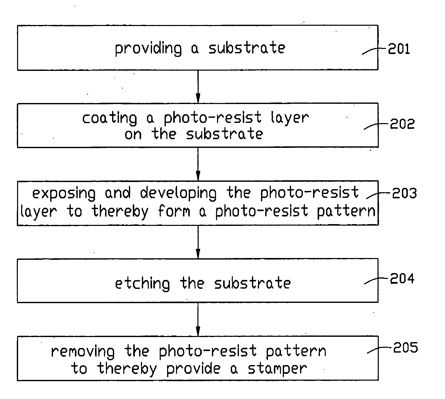
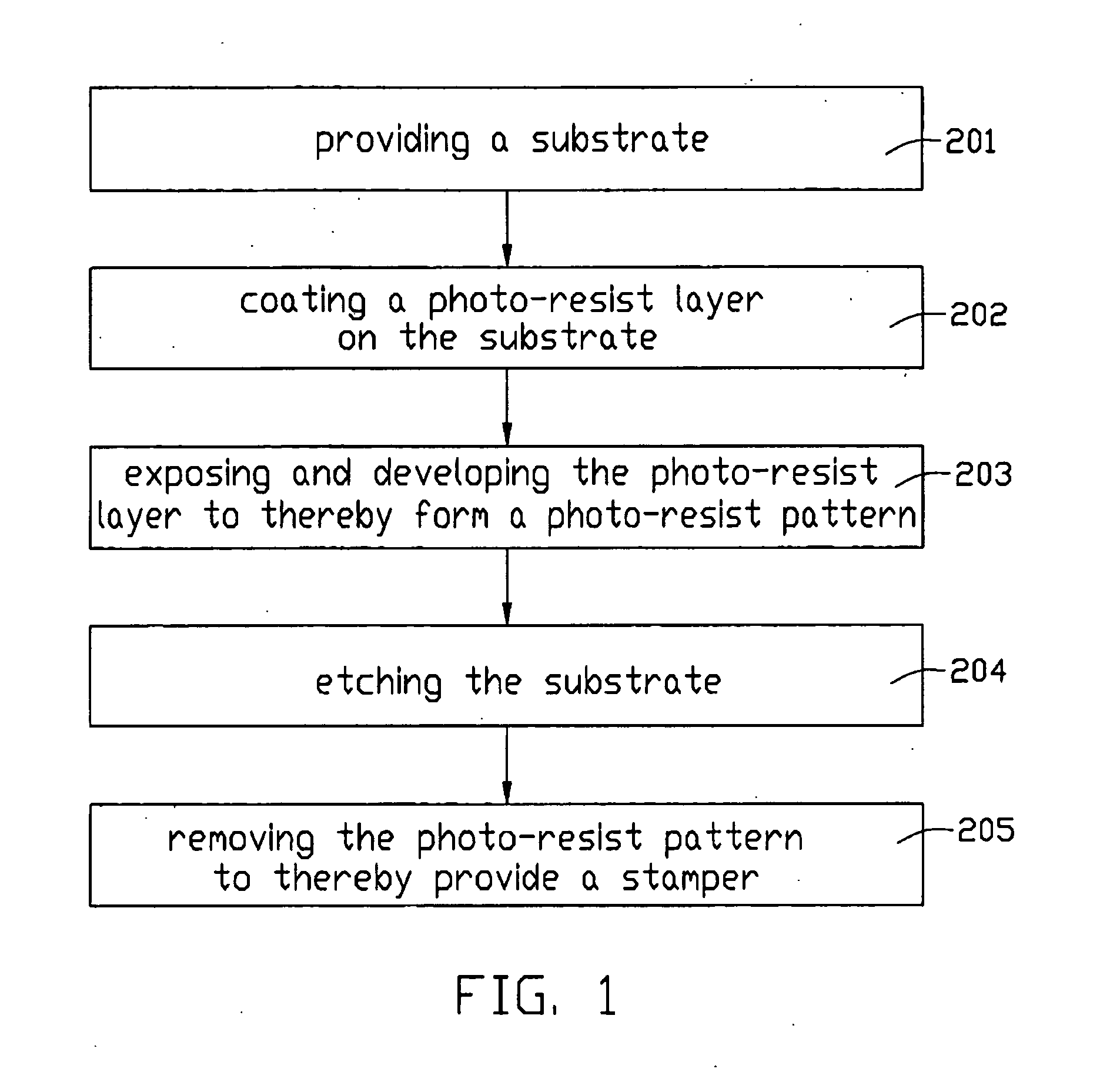
[0023] Referring to FIG. 1, a method for fabricating a stamper of the present invention includes five steps: (a) providing a substrate (step 201); (b) coating a photo-resist layer on the substrate (step 202); (c) exposing and developing the photo-resist layer using a photo-mask having a predetermined pattern to thereby form a photo-resist pattern (step 203); (d) etching the substrate (step 204); and (e) removing the photo-resist layer to thereby provide a stamper (step 205).

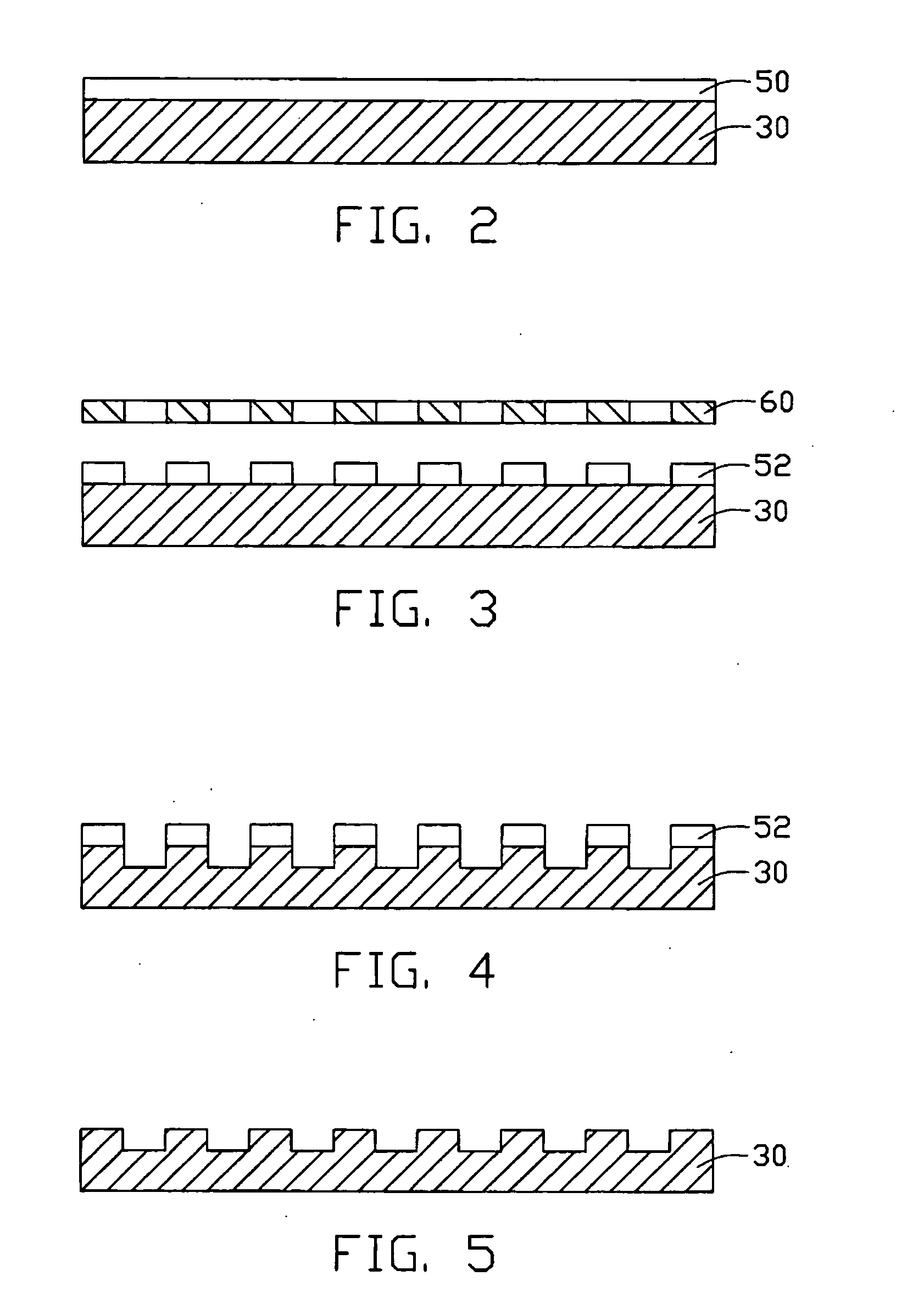
[0024] Referring to FIG. 2, in the first step, a substrate 30 is provided. The substrate 30 is a polished nickel sheet. The substrate 30 is baked in a vacuum or in a nitrogen environment at a temperature between 100° C. and 120° C. for 4˜6 minutes, in order to dehydrate the substrate 30. In the second step, a photo-resist layer 50 is coated on the substrate 30 by a spin-coating method or a spray-coating method. The photo-resist layer 50 is an organic, positive photo-resist. Then, the substrate 30 having the phot...


PUM

PropertyMeasurementUnit
thicknessaaaaaaaaaa
temperatureaaaaaaaaaa

Abstract

A method of for fabricating a stamper includes the following steps: (a) providing a substrate (30); (b) coating a photo-resist layer (50) on the substrate; (c) exposing and developing the photo-resist layer to form a photo-resist pattern (52); (d) etching the substrate; and (e) removing the photo-resist pattern to thereby provide the stamper. The method of the present invention does not require an electroforming step or create an electroformed layer. The formed stamper only includes a derivative of the substrate, which is made of nickel or steel. The substrate can have a large thickness, in order that the substrate has a high rigidity. Thus, the stamper resists distortion and has a long service life.

Description

BACKGROUND OF THE INVENTION [0001] 1. Field of the Invention [0002] The present invention relates to a method for fabricating a stamper, such as a stamper used for manufacturing light guide plates of liquid crystal displays. [0003] 2. Description of the Prior Art [0004] At present, stampers are widely utilized in many kinds of production processes, such as in the manufacture of light guide plates. Conventional methods for fabricating stampers take a long time. Generally, the whole period for fabricating a stamper from start to finish is approximately one month. Although methods for fabricating stampers are being improved, they cannot keep pace with the advances being made in related production processes which are much speedier. [0005] Taiwan patent publication No. 522263 discloses a method for fabricating a stamper. Referring to FIGS. 6 to 11, the method includes the following steps: (1) providing a conductive substrate 10; (2) coating a negative photo-resist layer 20 on the substra...

Claims


Application Information

Patent Timeline
Patent Type & Authority Applications(United States)
IPC IPC(8): B28B7/34B29D17/00G03F7/00
CPCG03F7/0015
Inventor CHEN, GA-LANEYU, TAI-CHERNGLEU, CHARLES
Owner HON HAI PRECISION IND CO LTD
Learn More