
Sanitary ware capable of automatic generation and charge

Inactive Publication Date: 2005-08-25
HSU CHI CHEN
View PDF2 Cites 1 Cited by
  • Summary
  • Abstract
  • Description
  • Claims
  • Application Information

AI Technical Summary

Benefits of technology

[0006] The primary object of the invention is to provide an instant great power required by accumulators, while hydraulic generator can continue power supply and the surplus power generated by the generator can be stored in the accumulator. Accordingly, the integral structure is neat without the requirement of installation of electric cord, reducing the electricity consumed by the sanitary ware.
[0009] The micro hydraulic generator is associated to the water outlet conduit of the sanitary ware, which is composed of a water flow pipe element combined with a generator set and a regulating mechanism. The water flow pipe element is interiorly composed of a reservoir and exteriorly composed of inlet and outlet pipes and associated to a generator set provided with a magnetic ring. The reservoir can contain a flap axle accompanied with a magnetic ring. By way of the dash of the flowing water on the flap axle, the magnetic ring provided in adaptation to the flap axle will generate magnetic actuation effect with the generator set, thereby generating power for regularly operating the magnetic valve.

Problems solved by technology

While dry cells require replacement after a period of time when the power has been consumed, the adopted power need additional cord installation, rendering considerable cost and troublesome installation, and incidentally, the danger of electric shock.
Meanwhile, in case the user lives in a remote district where power supply is not usually normal, it is worthy a consideration that the installation could be difficult, and that it might not be necessarily convenient to enjoy automatic flush on the urinal and automatic water supply from the faucet.
However, in view of the limitation in the volume of the power output from the micro hydraulic generator, and the incapability of supplying great power for the need of instant actuation of the magnetic valve, the micro hydraulic generator used to be applied to water heaters of water-actuating-fire without broadly utilized.

Method used


Image

  • Sanitary ware capable of automatic generation and charge
  • Sanitary ware capable of automatic generation and charge
  • Sanitary ware capable of automatic generation and charge

Examples


Embodiment Construction

[0020] The following descriptions are of exemplary embodiments only, and are not intended to limit the scope, applicability or configuration of the invention in any way. Rather, the following description provides a convenient illustration for implementing exemplary embodiments of the invention. Various changes to the described embodiments may be made in the function and arrangement of the elements described without departing from the scope of the invention as set forth in the appended claims.

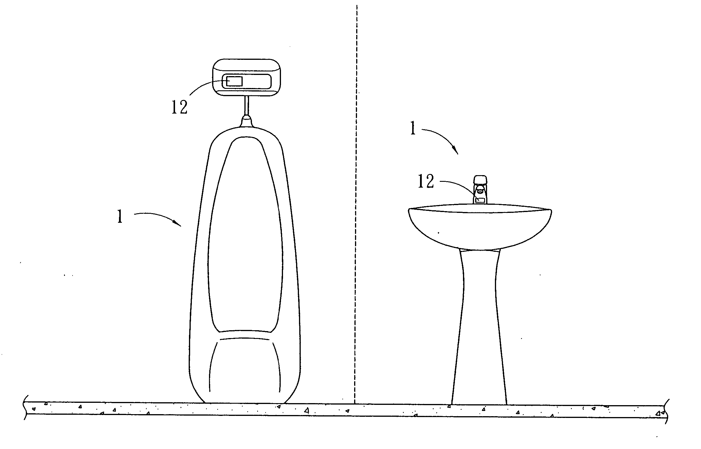
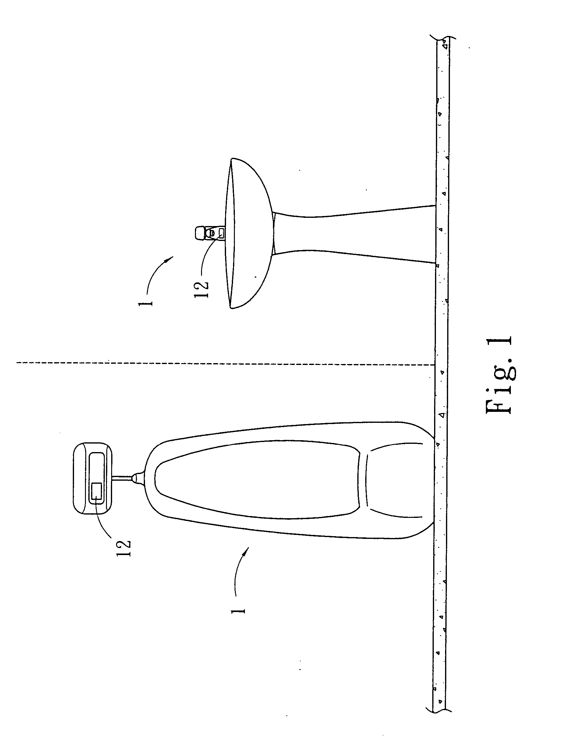
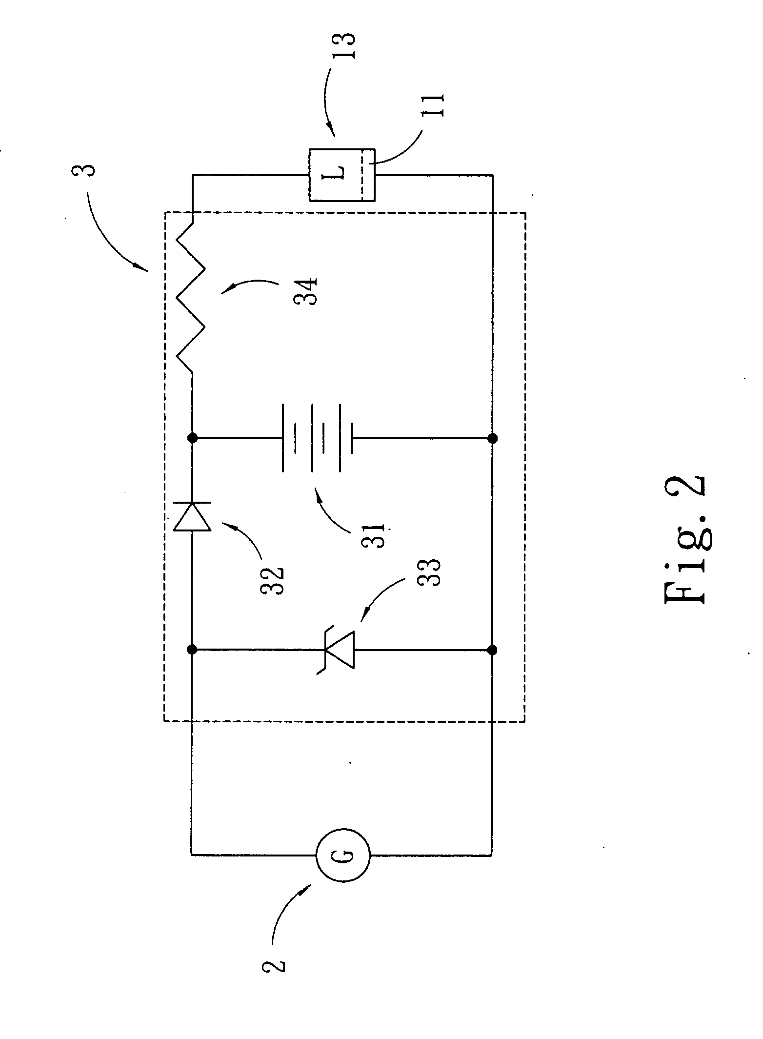
[0021]FIGS. 1 and 2 show an embodiment of the invention, which includes sanitary ware 1, a micro hydraulic generator 2 and charge control circuit 3.

[0022] The sanitary ware 1 is interiorly provided with a load 13, which has a magnetic valve 11 in association with a water outlet conduit for controlling the supply or stop of water.

[0023] Referring to FIG. 3, the micro hydraulic generator 2, being associated to the water outlet conduit, is composed of a housing 21 and a water flow pipe element f...


PUM


Abstract

A kind of sanitary ware capable of automatic generation and charge comprises sanitary ware, a micro hydraulic generator and a charge control circuit. The instant great power required of the sanitary ware is supplied by the accumulator, while the hydraulic generator can contain the power supply and store the surplus power in the accumulator. Thereby, the sanitary ware can automatically generate and charge for supplying the regular power that required by the operation of the magnetic valve. Given that the structure is simple and neat, and that the installation is easy, rendering the power consumption and the relevant cost can be relatively reduced, the invention is applicable to resident families, schools and public lavatories in remote districts where power supply is not easy to deliver.

Description

BACKGROUND OF THE INVENTION [0001] (a) Technical Field of the Invention [0002] The present invention relates to a kind of sanitary ware capable of automatic generation and charge, particularly to one that can supply power by way of an accumulator for instant great power use. The hydraulic generator can continue supplying power for use in sanitary ware and store surplus power in the accumulator. Given that the structure is simple and neat, and that the installation is easy, rendering the power consumption and the relevant cost can be relatively reduced, the invention is applicable to resident families, schools and public lavatories far away from cities and where not easy to receive power supply. [0003] (b) Description of the Prior Art [0004] The electrically controlled sanitary ware currently used, such as water heater of water-actuating-fire, urinal with a sensing flusher and an automatic water supply faucet for washbasin, is usually actuated by dry cells or adopted power. While dry...

Claims


Application Information

Patent Timeline
IPC IPC(8): E03C1/05E03D5/10
CPCE03D5/105E03C1/057
Inventor HSU, CHI-CHEN
Owner HSU CHI CHEN
Learn More