
Method For Visual Output Verification

a visual output and verification technology, applied in the field of user interfaces, can solve problems such as undesirable situation and inconvenient communication of information to users

Inactive Publication Date: 2005-08-18
INSULET CORP
View PDF99 Cites 419 Cited by
  • Summary
  • Abstract
  • Description
  • Claims
  • Application Information

AI Technical Summary

Benefits of technology

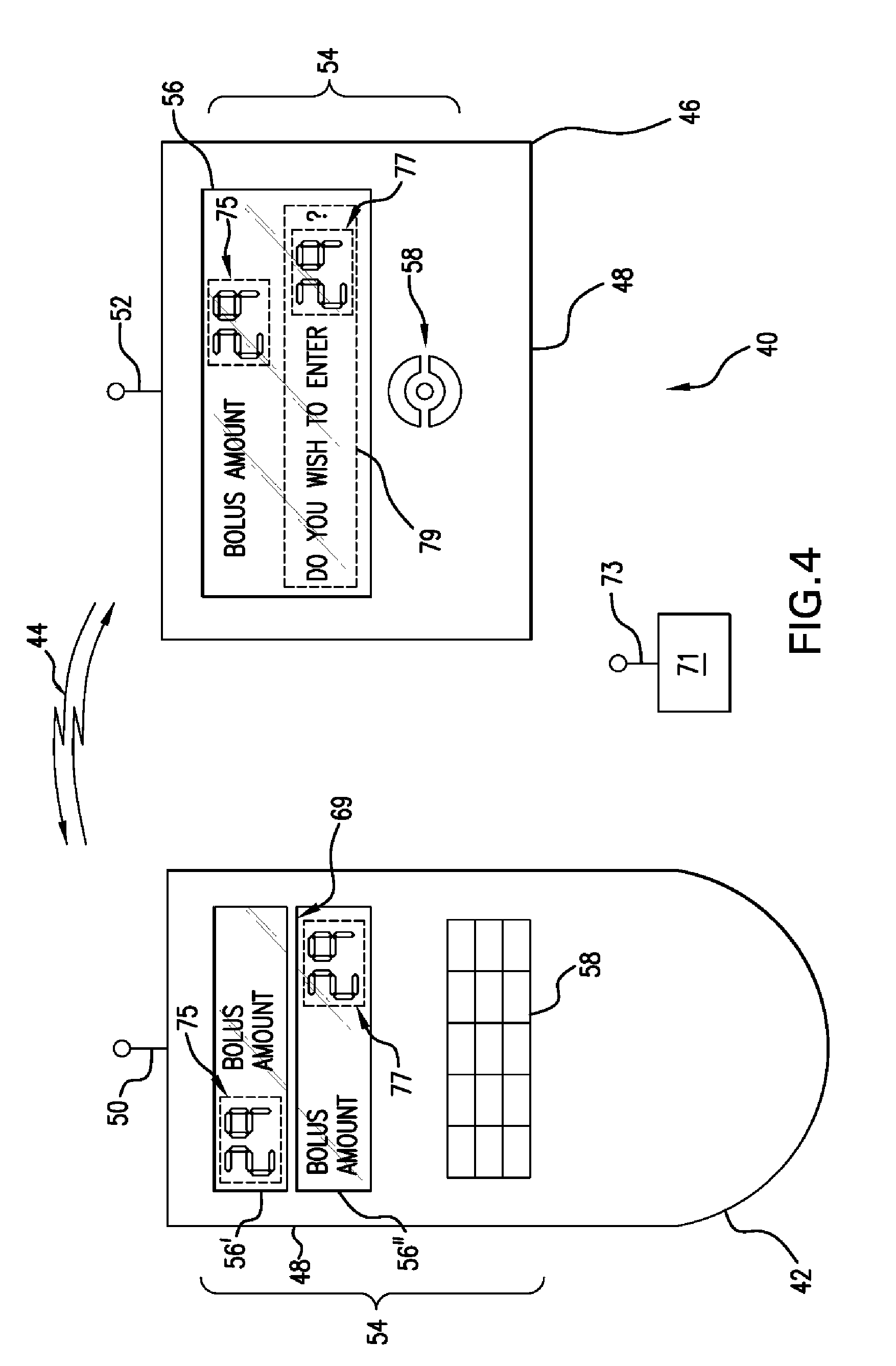
The present invention relates to a method and apparatus for verifying the correct operation of a user interface display device. The invention addresses the problem of malfunctioning segments or pixels in display devices, which can lead to incorrect information being communicated to the user. The invention proposes a method of displaying a visual output in two different regions of the user interface and receiving data from a separate device or input device. The method can quickly and easily alert the user to the malfunctioning of one or more segments or pixels of the display device. The invention is not limited to a specific system or method and can be used in various medical devices such as infusion pumps.

Problems solved by technology

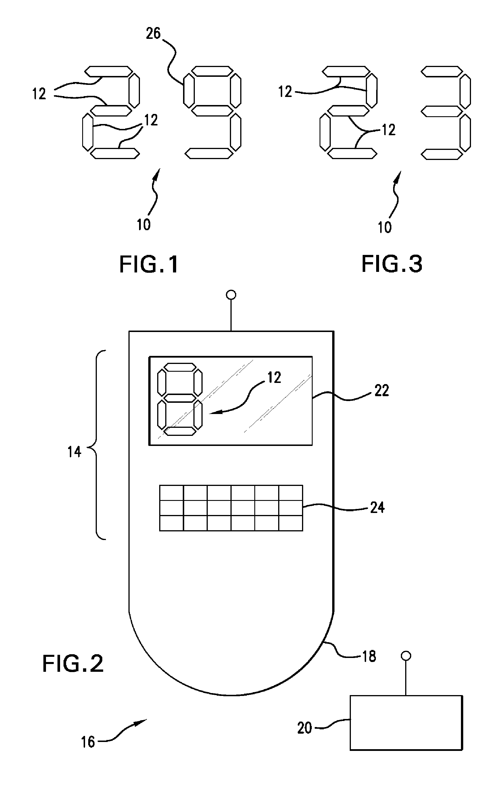
A problem with such display arrangements 10, however, is that one or more segments or pixels 12 can malfunction resulting in the incorrect information being communicated to the user.
This is particularly problematic with various medical apparatus where the display device 10 is used to display and input critical information.
It goes without need of further explanation that this situation is obviously undesirable, particularly with respect to medical devices.

Method used


Image

  • Method For Visual Output Verification
  • Method For Visual Output Verification
  • Method For Visual Output Verification

Examples


Embodiment Construction

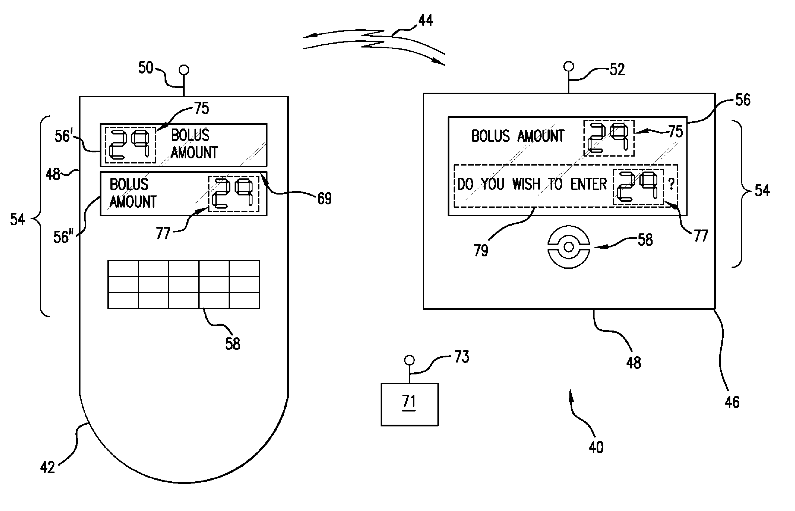
[0026] The present invention features a verification method and apparatus for verifying the correct operation of a display device such as a liquid crystal display (LCD) or the like. In the preferred embodiment, the method and apparatus preferably includes a medical device, though one skilled in the art will understand that the present invention is not limited to medical devices. While not an exhaustive list, in the exemplary embodiment the medical device includes an infusion system (either internal or external), a cardiac defibrillator, a neurostimulator, an x-ray machine, an EKG machine, a diagnostic device, a glucometer, a blood analyzer, an electrocautery device, an operating room table, a monitor, a laparoscopic controller, or the like, or a remote controller for use with one or more of the above-described medical devices. Additionally, the remote controller includes a dedicated remote controller as well as any other device capable of communicating with one or more medical devic...


PUM

PropertyMeasurementUnit
sizeaaaaaaaaaa
weightaaaaaaaaaa
areasaaaaaaaaaa

Abstract

A verification method including the steps of displaying a visual output in a first region of a user interface and displaying at least a portion of said visual output in at least a second region of said user interface, said at least a second region being different than said first region, wherein said first and said at least a second region are disposed on a single surface of a device.

Description

CROSS-REFERENCE TO RELATED APPLICATIONS [0001] This application is a continuation-in-part of and claims the benefit of U.S. patent application Ser. No. 10 / 827582, which was filed on Apr. 19, 2004, and which claimed the benefit of U.S. Provisional Patent Application Nos. 60 / 463809, filed Apr. 18, 2003, and 60 / 563579, filed on Apr. 19, 2004, all of which are incorporated by reference herein.TECHNICAL FIELD [0002] The present invention relates to user interfaces and more particularly, relates to method and apparatus for verifying the visual output of a user interface. BACKGROUND INFORMATION [0003] Numerous devices include a user interface having a display device. Such devices visually display information to a user or operator. While there are a variety of different display devices, one of the most common display devices includes a screen such as a liquid crystal displays (LCDs). LCDs offer many advantages over traditional cathode ray tubes (CRTs) such as reduced size, reduced weight, a...

Claims


Application Information

Patent Timeline
Patent Type & Authority Applications(United States)
IPC IPC(8): A01N31/00A61M37/00
CPCA61M5/142A61M2205/3561A61M2209/01A61M2205/502A61M2205/505A61M2205/3592
Inventor VOGT, MARCGEMMELL, STEPHEN
Owner INSULET CORP
Learn More