Supercharge Your Innovation With Domain-Expert AI Agents!

Printer head chip and printer head

a printer head and printer head technology, applied in the direction of printing, inking apparatus, etc., can solve the problems of large ink flow path b>8/b>, large overall size, complex structure, etc., and achieve the effect of discharging heat generated by the printer head chips

Inactive Publication Date: 2005-08-18
SONY CORP
View PDF4 Cites 2 Cited by
  • Summary
  • Abstract
  • Description
  • Claims
  • Application Information

AI Technical Summary

Benefits of technology

Simplifies the printer head structure, reduces size, achieves effective ink supply and cooling, and prevents ink wastage by allowing ink circulation and efficient bubble removal.

Problems solved by technology

Therefore, this type of printer head has problems in that its overall size becomes large and in that its structure becomes complicated due to the formation of the ink flow path 8.
Here, as regards a relatively small printer head like that used in a serial printer, the size is not a very serious problem, but as regards, in particular, a long printer head like that used in a line printer, there is a problem in that the ink flow path 8 becomes large due to the long printer head.
However, since the ink merely stays inside the ink flow path 8, there is a problem that a sufficient cooling effect cannot be provided.
This is because, when the bubbles break when the ink is compressed, sufficient force is no longer exerted upon ink drops i in the direction in which they are discharged, so that the ink drops i tend to be improperly discharged.
Therefore, there is a problem in that ink is wastefully consumed.

Method used


Image

  • Printer head chip and printer head
  • Printer head chip and printer head
  • Printer head chip and printer head

Examples


first embodiment

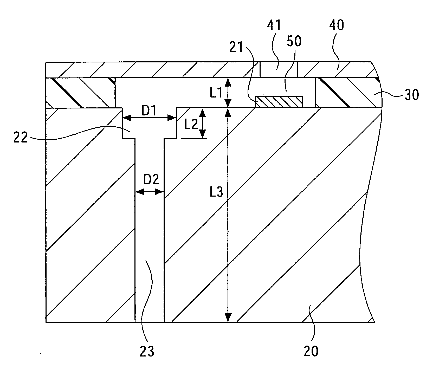
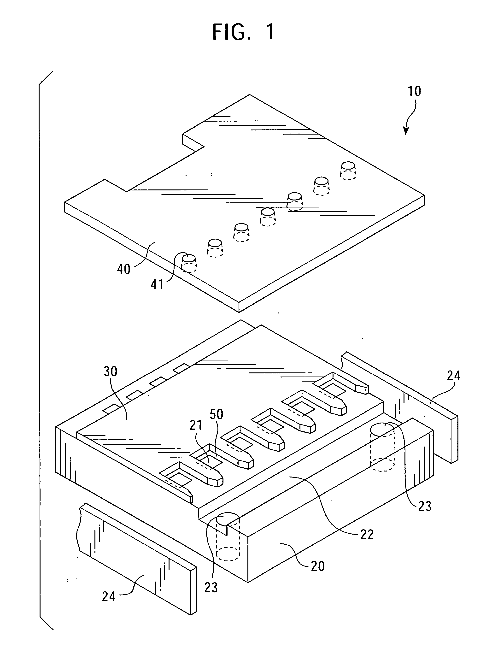
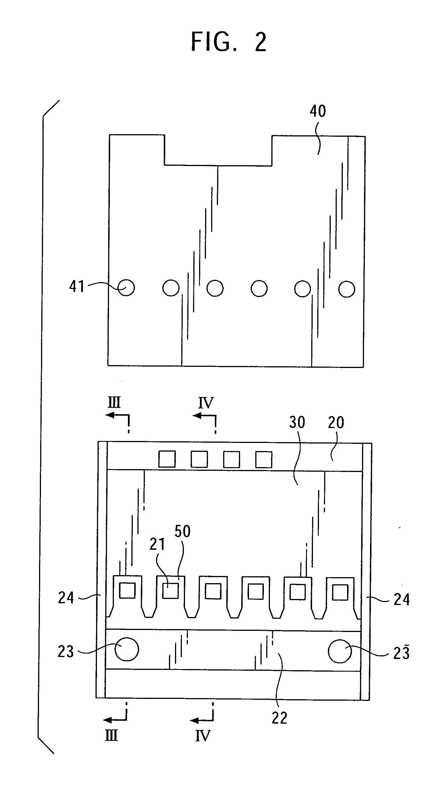
[0053] Hereunder, the present invention will be described with reference to the drawings. The first embodiment corresponds to the first to fourth aspects of the application. FIG. 1 is an exploded perspective view of a first embodiment of a printer head chip of the present invention. A printer head chip 10 is used in a printer head for a thermal inkjet printer.

[0054] The printer head chip 10 comprises a substrate 20, a film 30, and a nozzle sheet 40.

[0055] The substrate 20 is a semiconductor substrate formed of, for example, silicon. Heat-generating resistors (heaters) 21 are formed on one surface (the top surface in FIG. 1) of the substrate 20. The heat-generating resistors 21 are used to heat ink to be discharged.

[0056] Controlling of driving and the like of the heat-generating resistors 21 are carried out by the substrate 20. Although not shown, a logic integrated circuit (IC), a driver transistor, etc., are provided on the substrate 20.

[0057] The film 30 is placed upon the top...


PUM


Abstract

A printer head chip includes a plurality of ink compressing chambers which include heat-generating resistors and which are disposed side by side on a substrate. The printer head chip is used to discharge ink inside the plurality of ink compressing chambers from a nozzle by driving the heat-generating resistors. The printer head chip further includes an ink flow path groove, which is formed in the substrate and which is connected to each of the ink compressing chambers, for supplying ink to each of the ink compressing chambers. The invention makes it possible to supply ink to the printer head chip without increasing the size of a printer head, and to simplify the structure of the printer head.

Description

BACKGROUND OF THE INVENTION [0001] 1. Field of the Invention [0002] The present invention relates to a printer head chip suitable for use in, for example, an inkjet printer, and a printer head using the printer head chip. [0003] 2. Description of the Related Art [0004] A printer head of a type which discharges ink drops through a nozzle by generating pressure of ink bubbles inside an ink compressing chamber by heating a heat-generating resistor provided inside the ink compressing chamber is conventionally known. FIG. 11 is a sectional view of an example of a related printer head of this type. [0005] In FIG. 11, a printer head chip 1 of the printer head includes a substrate 2, heat-generating resistors (heaters) 3 formed on the substrate 2, ink compressing chambers 4, and nozzles 5 formed at the top portions of the ink compressing chambers 4. [0006] The heat-generating resistors 3 are used to compress ink that fills the inside of the ink compressing chambers 4 by the heat of the heat...

Claims


Application Information

Patent Timeline
Patent Type & Authority Applications(United States)
IPC IPC(8): B41J2/14B41J2/155
CPCB41J2/1404B41J2/14145B41J2202/20B41J2002/14387B41J2202/12B41J2/155
Inventor EGUCHI, TAKEOKOHNO, MINORUHORII, SHINICHINAMEKAWA, TAKUMI
Owner SONY CORP
Features
  • R&D
  • Intellectual Property
  • Life Sciences
  • Materials
  • Tech Scout
  • Unparalleled Data Quality
  • Higher Quality Content
  • 60% Fewer Hallucinations
Learn More