
Gutter and downspout system for a tent or shelter

Inactive Publication Date: 2005-08-18
THE COLEMAN CO INC
View PDF4 Cites 21 Cited by
  • Summary
  • Abstract
  • Description
  • Claims
  • Application Information

AI Technical Summary

Benefits of technology

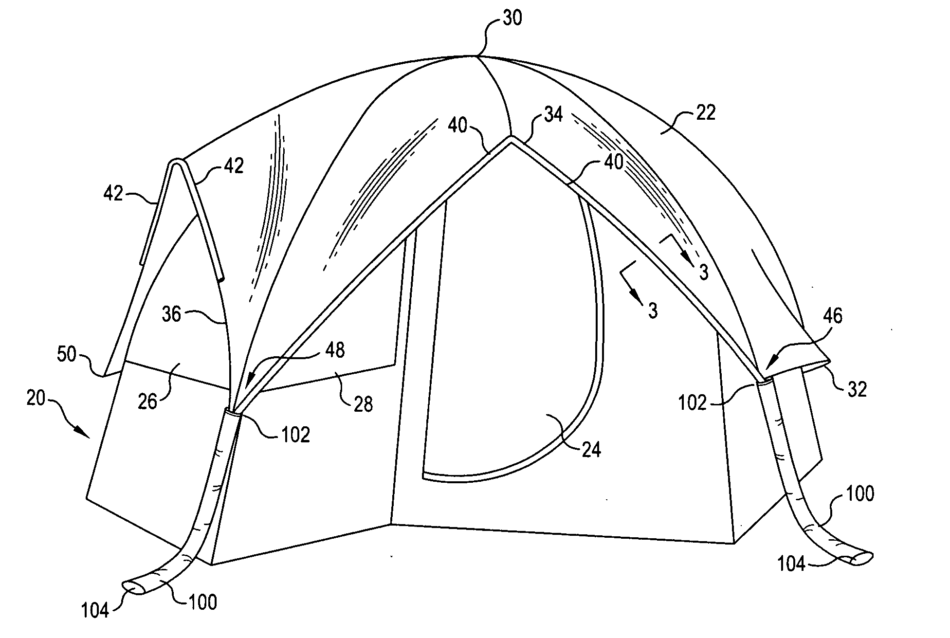
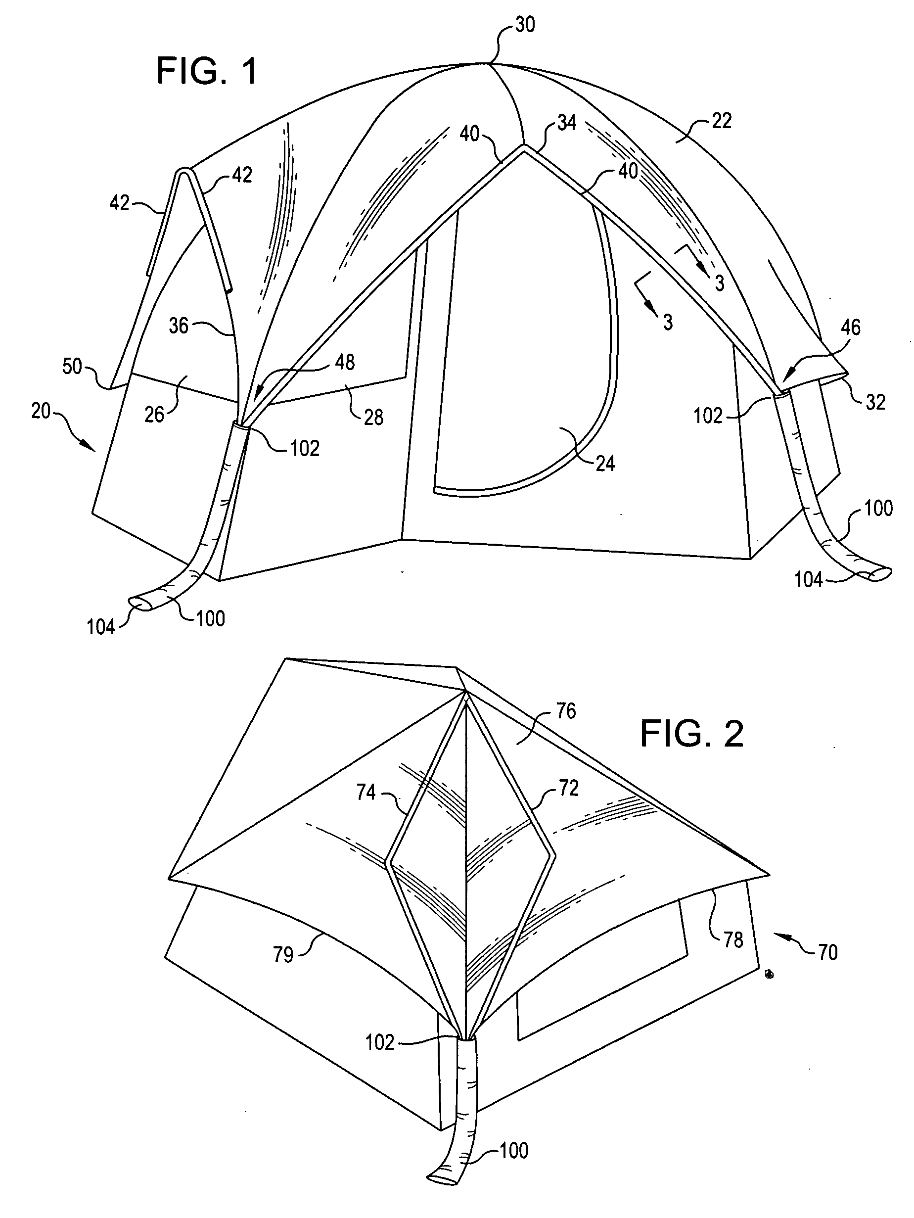
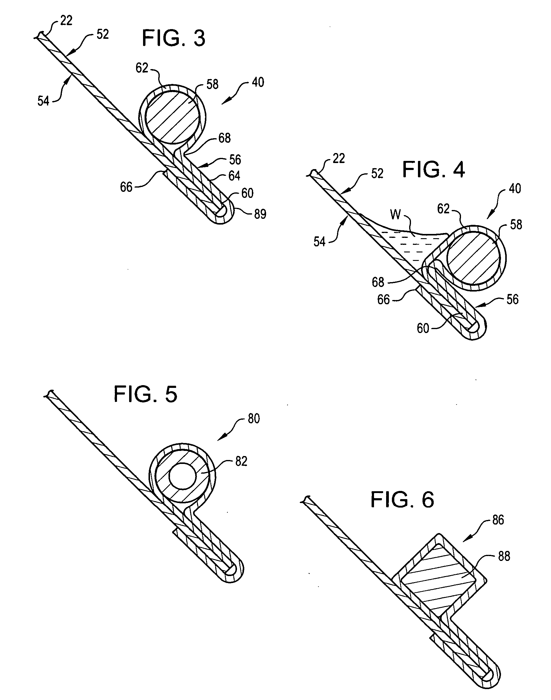
[0007] In accordance with an embodiment of the invention, a gutter and downspout system is provided that may be used with a tent, shelter, or other fabric structure. As one example, the gutter may be aligned along a rain fly edge to direct water away from the tent door or tent windows. After the rainwater is directed the proper distance to clear the tent door and / or windows, the water can fall from the rain fly to the ground. Alternatively, in accordance with an aspect of the invention, the rainwater may be directed via a downspout to the ground. Thus, a camper can enter or exit the tent through the door without the water dripping on the camper. In addition, windows may be left partially open during a rain shower without the rainwater runoff entering the tent through the open window(s). Also, rainwater flow off a shelter may be controlled and / or directed.
[0009] In accordance with an embodiment of the invention, a downspout may be provided that enhances water control of rainwater runoff. The downspout may include, for example, a flexible ring at an upper portion connected to an elongate waterproof fabric tube. The end of the tube may be arranged and directed as wanted. The attachment of the downspout to a rain fly or shelter canopy may be permanent or removable. The downspout directs rainwater runoff completely away from the tent or shelter area so that pooling or accumulation of water under or around the tent or shelter is eliminated.

Problems solved by technology

However, one problem with the use of such coverings is that water draining off of a rain fly or a shelter canopy may drip in undesirable areas, such as at a tent door or at tent windows.
In addition, a hard rain may cause a large amount of water to flow off of a covering and may cause considerable splashing or splatter, especially for shelters, which typically have canopies that are spaced higher from the ground than a tent rain fly.

Method used


Image

  • Gutter and downspout system for a tent or shelter
  • Gutter and downspout system for a tent or shelter
  • Gutter and downspout system for a tent or shelter

Examples


Embodiment Construction

[0017] In the following description, various embodiments of the present invention will be described. For purposes of explanation, specific configurations and details are set forth in order to provide a thorough understanding of the embodiments. However, it will also be apparent to one skilled in the art that the present invention may be practiced without the specific details. Furthermore, well-known features may be omitted or simplified in order not to obscure the embodiment being described.

[0018] Referring now to the drawings, in which like reference numerals represent like parts throughout the several views, FIG. 1 shows a tent 20 incorporating an embodiment of the invention. The tent 20 shown in the drawings is a simplified model, and poles and specific details for the tent 20 are not shown. However, the general configuration and manufacture of tents is known, and thus a specific configuration is omitted or simplified in order to not obscure the embodiments of the invention bein...


PUM


Abstract

A gutter and downspout system that may be used with a tent, shelter, or other fabric structure. The gutter may be aligned along a rain fly edge to direct water away from the tent door or tent windows. After the rainwater is directed the proper distance to clear the tent door and / or windows, the water can fall from the rain fly to the ground or may be directed via a downspout to the ground. The gutter is formed of a flexible material that is sewn to the rain fly or to the canopy. The downspout may include, for example, a flexible ring at an upper portion connected to an elongate waterproof fabric tube. The end of the tube may be arranged and directed as wanted.

Description

TECHNICAL FIELD OF THE INVENTION [0001] The present invention generally relates to tents and shelters, and more particularly to tent and shelter construction. BACKGROUND OF THE INVENTION [0002] Camping is a popular recreational activity enjoyed by many. Some people camp so that they may enjoy the outdoors, and others use camping as an inexpensive alternative to staying in a hotel. [0003] Typically, campers sleep in a tent while camping. Tents are portable shelters made of lightweight, often waterproof, fabrics. Typically, the fabric is stretched over and sustained by a frame. Tents are used for camping outdoors or as temporary structures, and come in a variety of shapes and sizes. The most popular shape is the dome, or free standing, model. This model is easy to set up and does not require support from tree limbs or other objects. [0004] Another structure that is often used while camping is a shelter. In general, a shelter is a structure, typically a frame with poles, that includes ...

Claims


Application Information

Patent Timeline
IPC IPC(8): E04H15/32E04H15/54
CPCE04H15/54E04H15/32
Inventor HOLUB, TIMOTHY M.
Owner THE COLEMAN CO INC
Learn More