Conveying member, especially rotor or stator, for conveying a flowable, preferably gaseous medium
- Summary
- Abstract
- Description
- Claims
- Application Information
AI Technical Summary
Benefits of technology
Problems solved by technology
Method used
Image
Examples
Embodiment Construction
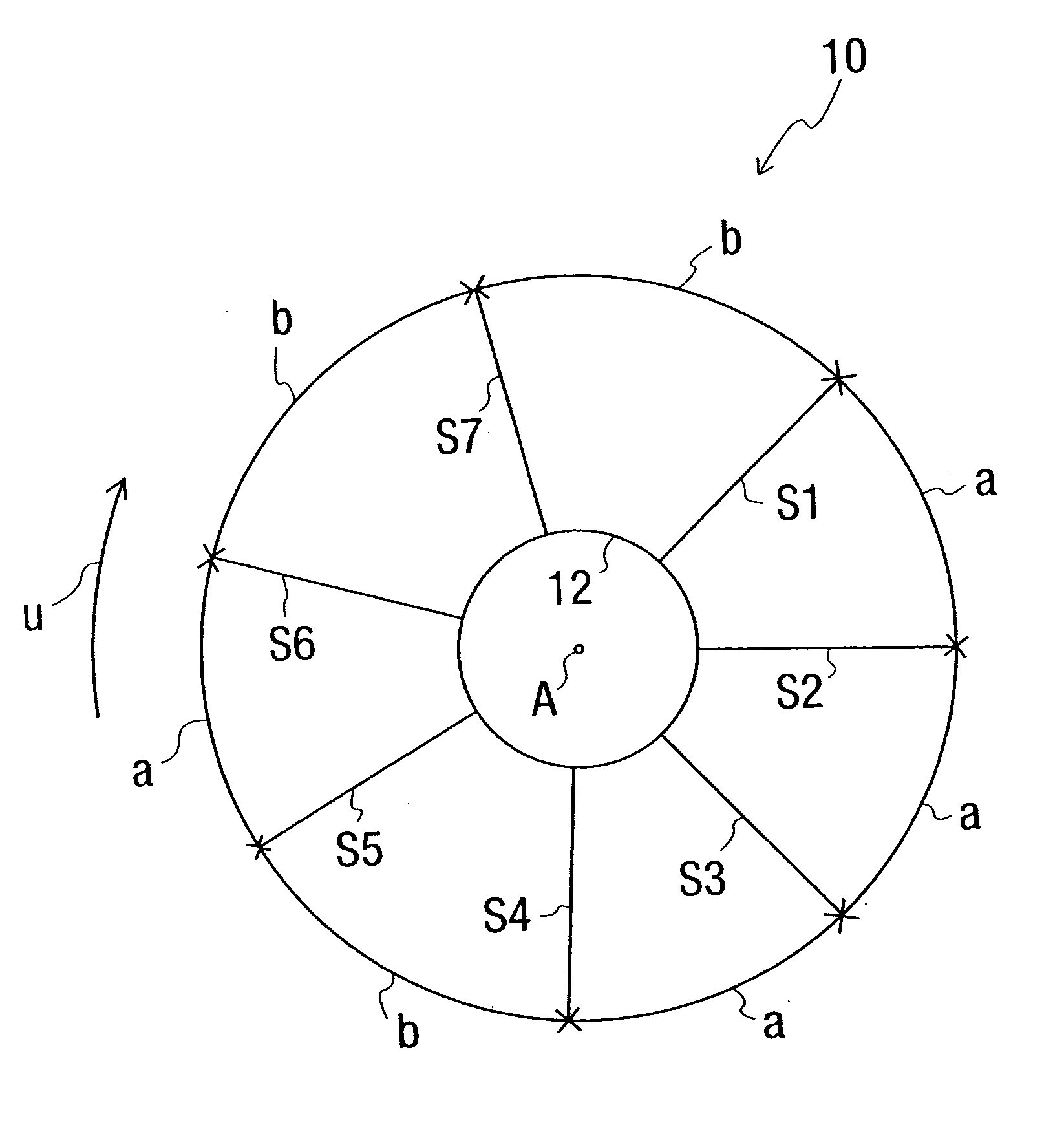
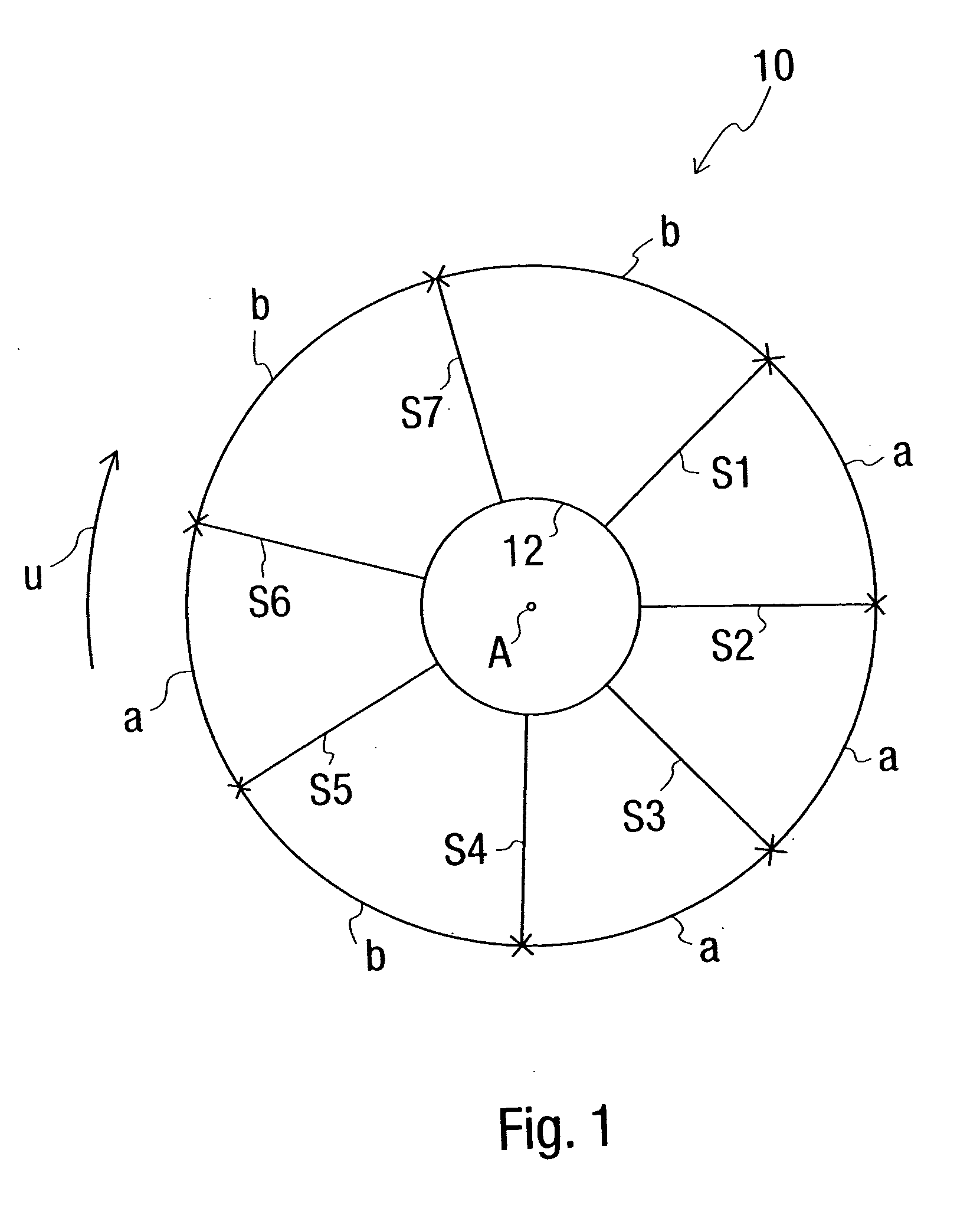
[0027] The design of the conveying member according to the present invention will be described below in reference to a conveying wheel generally designated by 10 in FIG. 1, as it can be used, for example, in a so-called side channel fan. The more specific design of such a side channel fan, which is known per se, will not be explained in greater detail here. However, reference is made in this connection, for example, to DE 39 39 957 A1, which was mentioned in the introduction and shows this general design.
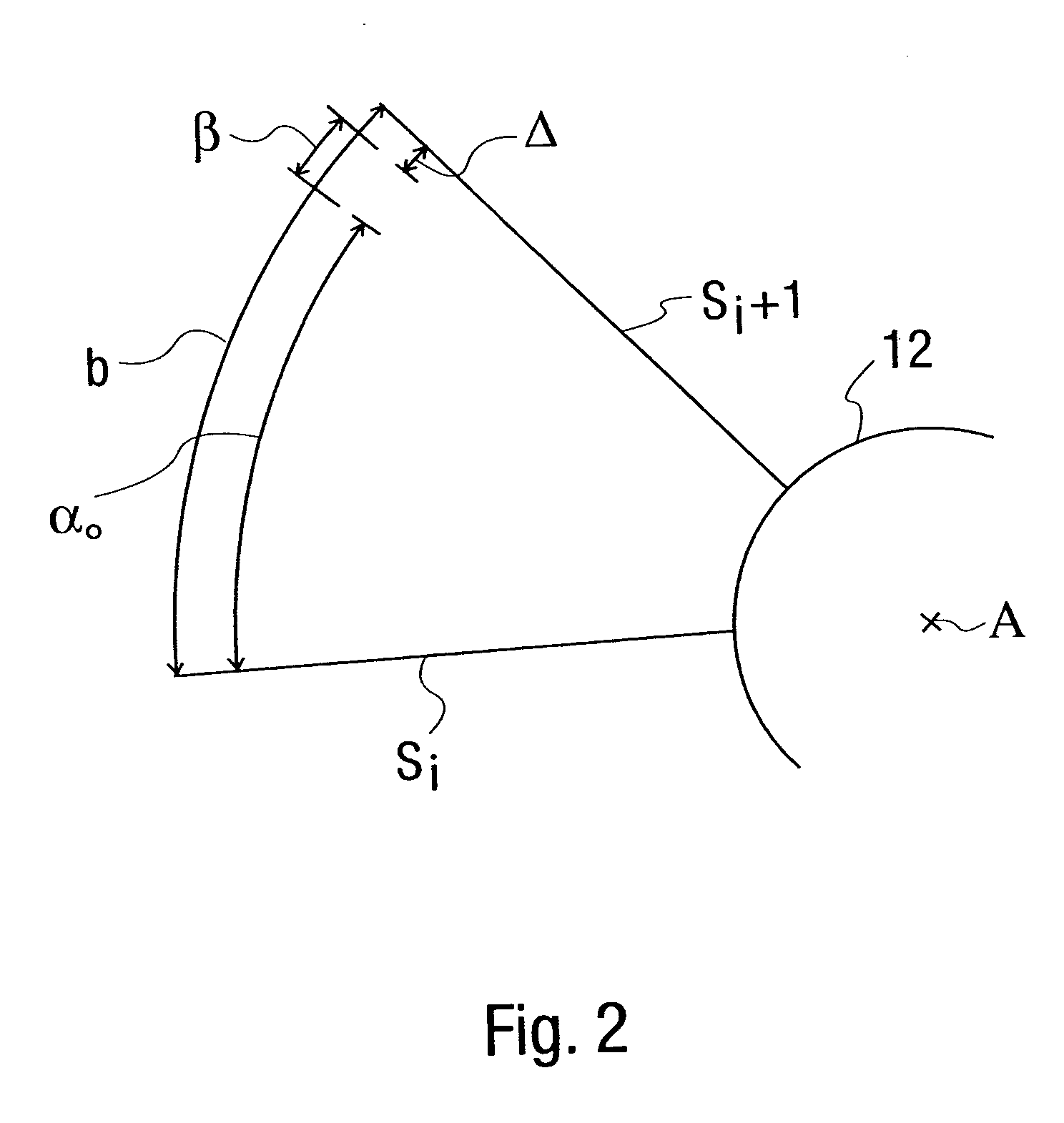
[0028] On a hub 12, which represents equally a shell or a housing of the conveying wheel 10, the conveying wheel 10 according to the present invention has a plurality of blades S1-S7 distributed in such a way that they follow each other in the circumferential direction around an axis of rotation or a center A of this conveying wheel 10. It can be recognized that the blades directly following each other in the circumferential direction U have either a circumferential distance a or a...
PUM
 Abstract
Description
Claims
Application Information
 - R&D
- Intellectual Property
- Life Sciences
- Materials
- Tech Scout
- Unparalleled Data Quality
- Higher Quality Content
- 60% Fewer Hallucinations
Browse by: Latest US Patents, China's latest patents, Technical Efficacy Thesaurus, Application Domain, Technology Topic, Popular Technical Reports.
© 2025 PatSnap. All rights reserved.Legal|Privacy policy|Modern Slavery Act Transparency Statement|Sitemap|About US| Contact US: help@patsnap.com


