
Image coding apparatus, image decoding apparatus, image display apparatus and image processing apparatus

a technology of image processing and coding apparatus, applied in the field of image coding technology and image decoding technology, can solve the problems of reducing the amount of computation, reducing the number of potentialities, and coding processing takes a longer time, and achieve the effect of extra cos

Active Publication Date: 2005-08-11
PANASONIC INTELLECTUAL PROPERTY CORP OF AMERICA
View PDF16 Cites 87 Cited by
  • Summary
  • Abstract
  • Description
  • Claims
  • Application Information

AI Technical Summary

Benefits of technology

[0023] The present invention has been made in view of the foregoing circumstances and problems, and an object thereof is to provide an image coding and decoding technology capable of coding part of the region of an image in preference to the rest thereof and decoding the coded image data, without an extra cost.

Problems solved by technology

Motion-JPEG2000, when compared with MPEG (Moving Picture Experts Group) and other moving image coding specifications, is inferior in compression ratio because of its inability to use frame correlation, but is superior in its capacity for editing in frame units and reversible coding, thus holding numerous potentialities.
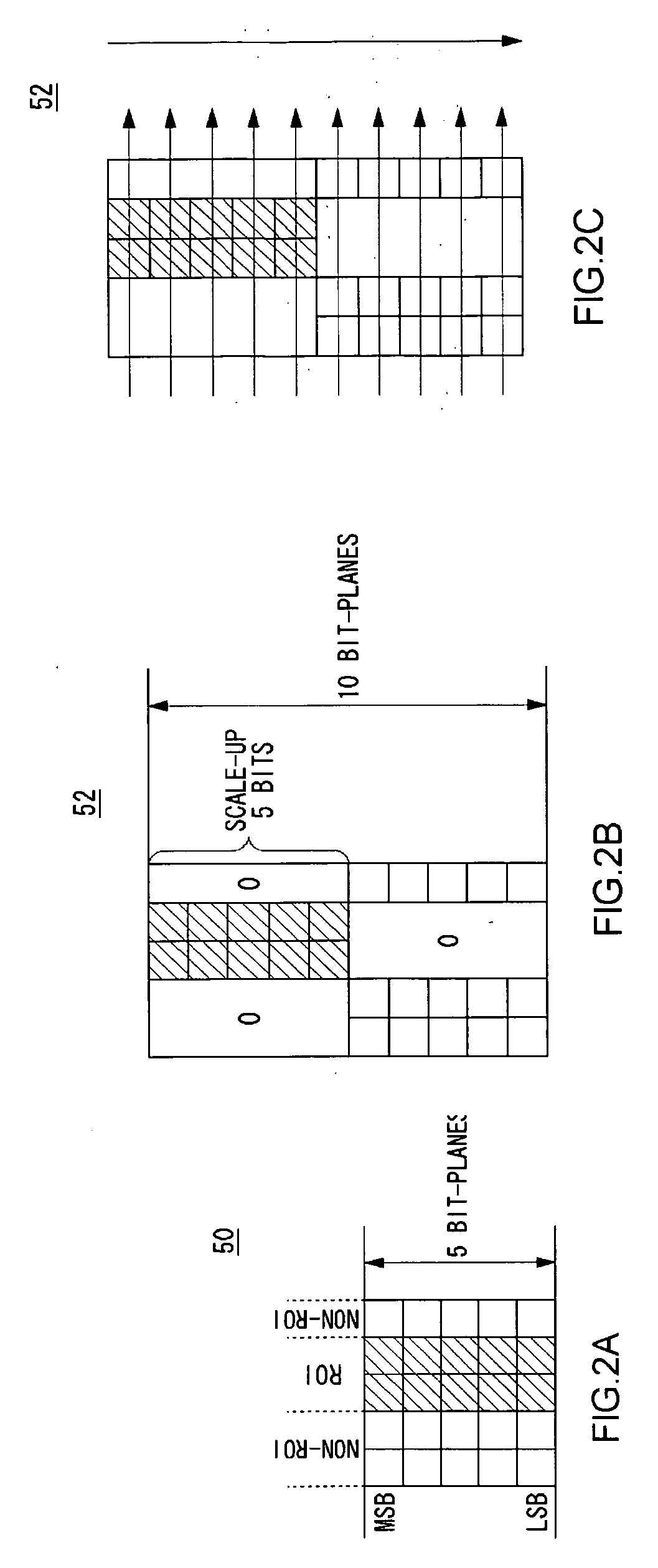
Moreover, the coding processing takes a longer time because an excess coding must be carried out for the scaled-up bit-planes.
As described above, the conventional ROI coding has problem and drawback in that it involves a scale-up processing, which requires an excess memory capacity and an eventual increase in the amount of computation.
The conventional ROI coding as described above also has a problem in that when there are a plurality of regions of interest, it cannot provide any difference in image quality among the plurality of regions of interest.
Among such images to be distributed, however, there may be images, like those of a surveillance camera, which requires higher image quality for a certain part of them and not so high quality for the remaining part of them.
Furthermore, when a region specified by the user is set for a higher image quality, there may be cases where the image processing capacity is exceeded due to the increase in the amount of processing, thus resulting in the drop of frames.

Method used


Image

  • Image coding apparatus, image decoding apparatus, image display apparatus and image processing apparatus
  • Image coding apparatus, image decoding apparatus, image display apparatus and image processing apparatus
  • Image coding apparatus, image decoding apparatus, image display apparatus and image processing apparatus

Examples


first embodiment

[0111]FIG. 5 illustrates a structure of an image coding apparatus 200 according to a first embodiment of the present invention. In terms of hardware, this structure of image coding apparatus 200 can be realized by a CPU, a memory and other LSIs of an arbitrary computer. In terms of software, it can be realized by memory-loaded programs which have coding functions or the like, but drawn and described herein are function blocks that are realized in cooperation with those. Thus, it is understood by those skilled in the art that these function blocks can be realized in a variety of forms such as by hardware only, software only or the combination thereof.

[0112] The image coding apparatus 200 performs compression and coding of inputted original images, which serve as an example, by JPEG2000 scheme. Original images inputted to the image coding apparatus 200 may be frames of moving images. The image coding apparatus 200 can encode sequentially each frame of moving images and generate codes...

second embodiment

[0137]FIG. 10 illustrates a structure of an image decoding apparatus 220 according to a second embodiment of the present invention. According to this second embodiment, a coded image to be inputted to the image decoding apparatus 220 is an ordinary coded image, which has not been subjected to a ROI coding. The image decoding apparatus 220 according to this second embodiment specifies a region of interest at decoding and decodes the region of interest on a preferential basis.

[0138] Coded images to be inputted to the image decoding apparatus 220 may also be coded frames of moving images. A moving image can be reproduced by consecutively decoding coded frames of the moving image, which are inputted as a codestream.

[0139] A coded data extracting unit 30 extracts coded data from an inputted coded image, and an entropy decoding unit 32 decodes the coded data bit-plane by bit-plane and stores the resulting quantized wavelet transform coefficients in a memory.

[0140] A ROI selector 18 sel...

third embodiment

[0149]FIG. 12 illustrates a structure of an image coding apparatus 200 according to a third embodiment of the present invention. With an image coding apparatus 200 according to the first embodiment, a single region of interest only is selected, but an image coding apparatus 200 according to this third embodiment selects a plurality of regions having different degrees of priority in an image, performs compression and coding of the image according to the degrees of priority thereof, and generates a coded image having a plurality of regions with different image qualities. Hereinbelow, the same reference numerals will be used for a structure equal to that of the first embodiment, and the structure and operation different from those of the first embodiment will be described.

[0150] A ROI selector 18 selects a plurality of regions of interest in an original image and supplies ROI position information indicative of the positions of the respective regions of interest to a ROI mask generator...


PUM


Abstract

A wavelet transform unit performs a wavelet transform on original images and a quantization unit quantizes wavelet transform coefficients. A ROI selector selects a region of interest or regions of interest in the original image, and a ROI mask generator generates ROI masks with which the wavelet transform coefficients (which are also called ROI transform coefficients) corresponding to the regions of interest are specified. By referring to the ROI masks, a lower-bit zero substitution unit substitutes low-order bits of non-ROI transform coefficients with zeros. An entropy coding unit entropy-codes the wavelet transform coefficients sequentially from high-order bit-planes, after the substitution. A coded data generator turns coded data into streams together with parameters and then outputs coded images.

Description

BACKGROUND OF THE INVENTION [0001] 1. Field of the Invention [0002] The present invention relates to an image coding technology and an image decoding technology, and it particularly relates to method and apparatus for preferentially coding or decoding a partial region of an image. The present invention further relates to an image display apparatus and an image displaying method, and relates also to apparatus for reproducing image streams. [0003] 2. Description of the Related Art [0004] At ISO / ITU-T, JPEG2000 using a discrete wavelet transform (DWT) is being standardized as a successor to JPEG (Joint Photographic Expert Group), which is a standard technology for compression and coding of still images. In JPEG2000, a wide range of image quality, from low bit-rate coding to lossless compression, can be coded highly efficiently, and a scalability function, in which the image quality is gradually raised, can be realized easily. Moreover, JPEG2000 comes with a variety of functions which t...

Claims


Application Information

Patent Timeline
IPC IPC(8): G06K9/36H04N1/41H04N7/26H04N7/30
CPCH04N19/647H04N19/63H04N19/127H04N19/126H04N19/1883H04N19/162H04N19/17H04N19/184H04N19/156
Inventor TAKETA, KAZUHIKOOKADA, SHIGEYUKI
Owner PANASONIC INTELLECTUAL PROPERTY CORP OF AMERICA
Learn More