Viewing angle control element and image display based on same
a control element and angle technology, applied in the direction of polarising elements, identification means, instruments, etc., can solve the problems of image darkness and difficult recognition, and achieve the effect of preventing the degrading of image quality by falling brightness of the image display elemen
- Summary
- Abstract
- Description
- Claims
- Application Information
AI Technical Summary
Benefits of technology
Problems solved by technology
Method used
Image
Examples
embodiment 2
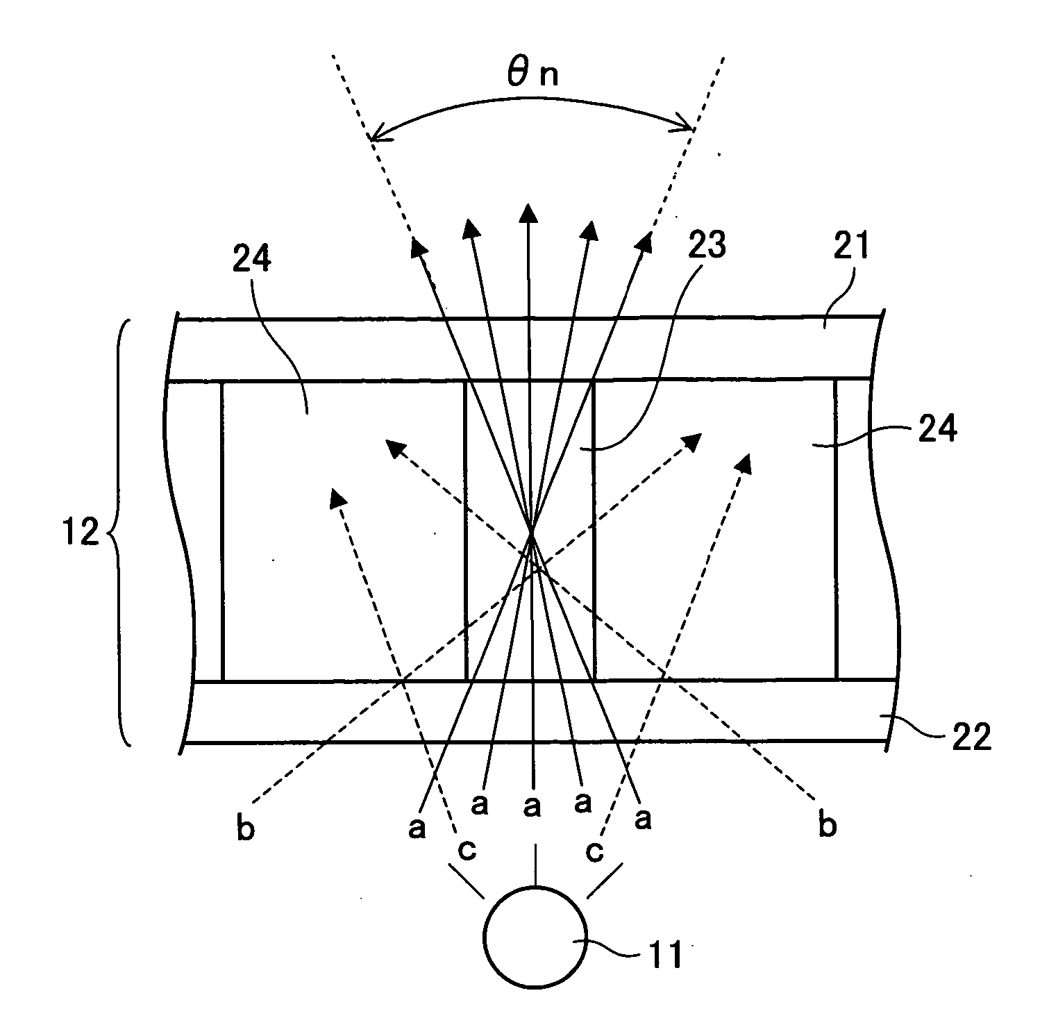
[0112] Next, referring to FIG. 4 and FIG. 5, principles in producing displays on the image display of the present embodiment will be described. In the present embodiment, the light shield regions 24 are formed of a polymer-dispersed liquid crystal.
[0113]FIG. 4 is an enlarged cross-sectional view of the image display of the present embodiment, illustrating principles in producing displays in narrow viewing angle mode. Display principles will be described in reference to FIG. 4.
[0114] Light, upon entering the viewing angle control element 12, is diffused, but not polarized. Of the light beams incident to the transparent region 23 which is a pillared transparent resin layer in the viewing angle control element 12, beams (a) within the angle θn (see the figure) leave the viewing angle control element 12, unaffected by the polymer-dispersed liquid crystal provided in the light shield region 24.
[0115] Meanwhile, relatively highly diffused beams (b) outside the angle θn (see the figure)...
examples
[0130] To illustrate the viewing angle control element 12 of the present invention more specifically, examples of the present invention will be now given. The viewing angle control elements 12 in the examples were fabricated by the following steps. First, a laminator of a negative resist for a thick film (product name: “ASF series” available from Hitachi Chemical Co., Ltd.) was transferred on to the glass substrate 2 provided with ITO (not shown) by high temperature substrate overheat. The laminator was exposed using a photo mask to form a desired pattern of a pillared transparent resin layer for the viewing angle control element 12. Under these circumstances, the laminator was exposed to ultraviolet rays (quantity: 200 mJ), developed for 1 minute in an 2% aqueous solution of NaOH at 30° C., washed, and baked for 40 minutes at 230° C. in a clean oven, to form a stripe pattern of the pillared transparent resin layer measuring 40 μm in thickness and 12 μm in width.
[0131] Next, an ali...
PUM
| Property | Measurement | Unit |
|---|---|---|
| thickness | aaaaa | aaaaa |
| thickness | aaaaa | aaaaa |
| transparent | aaaaa | aaaaa |
Abstract
Description
Claims
Application Information
 - R&D
- Intellectual Property
- Life Sciences
- Materials
- Tech Scout
- Unparalleled Data Quality
- Higher Quality Content
- 60% Fewer Hallucinations
Browse by: Latest US Patents, China's latest patents, Technical Efficacy Thesaurus, Application Domain, Technology Topic, Popular Technical Reports.
© 2025 PatSnap. All rights reserved.Legal|Privacy policy|Modern Slavery Act Transparency Statement|Sitemap|About US| Contact US: help@patsnap.com


