Inverter control apparatus and inverter control method
a control apparatus and inverter technology, applied in the direction of electronic commutators, motor/generator/converter stoppers, dynamo-electric converter control, etc., can solve the problem of reducing the time period for the a/d conversion of all phases, reducing the accuracy of the a/d-converter motor current, and preventing abnormal overheating. , the effect of high reliability
- Summary
- Abstract
- Description
- Claims
- Application Information
AI Technical Summary
Benefits of technology
Problems solved by technology
Method used
Image
Examples
first embodiment
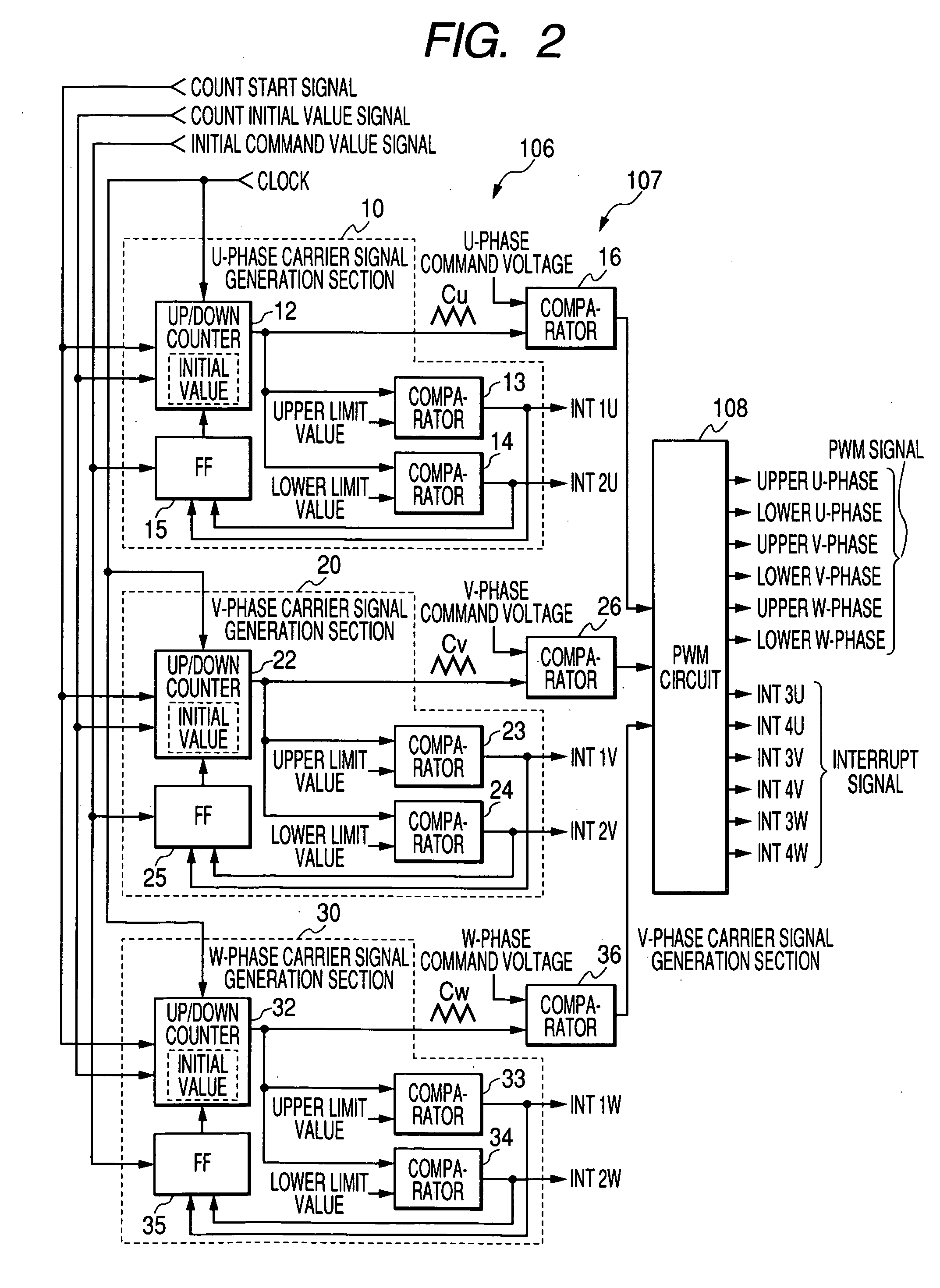
[0079]FIG. 1 shows an inverter control apparatus of a first embodiment of the invention. In the drawing, B denotes a battery. A power is supplied from the battery B to a motor M via a contactor Z and an inverter circuit 100. The motor M is a three-phase induction motor which is mounted on, for example, a forklift. The contactor Z is configured by contacts of an electromagnetic contactor. In the drawing, C denotes a capacitor which is connected between power lines, ST denotes a shunt which is used for detecting the current flowing through the motor M, which is configured by resistors, and which corresponds to the current detection method in the invention, and PG denotes a pulse generator which is used for detecting the revolution of the motor M, and which is configured by a known rotary encoder disposed on the rotary shaft of the motor M.
[0080] The inverter circuit 100 is a known circuit which converts the DC power source of the battery B to an AC power source to drive the motor M, ...
second embodiment
[0132] Next, a second embodiment of the invention will be described in detail.
[0133]FIG. 17 shows an example of an inverter control apparatus of the second embodiment of the invention. The components which are identical with those in the configuration of the first embodiment shown in FIG. 1 are denoted by the same reference numerals, and their detailed description is omitted.
[0134] In the second embodiment, shunts ST1 to ST3 are disposed in place of the shunt ST in FIG. 1. The shunts ST1 to ST3 detect the currents of the phases (U-phase, V-phase, and W-phase) flowing through the motor M, respectively.
[0135] An inverter circuit 500 is a known circuit which converts the DC power source of the battery B to an AC power source to drive the motor M, and which is configured by the six semiconductor switching elements Q1 to Q6 of U-phase upper, U-phase lower, V-phase upper, V-phase lower, W-phase upper, and W-phase lower. The shunt ST1 is connected in series to the series connection of t...
third embodiment
[0158] Next, a third embodiment of the invention will be described in detail.
[0159]FIG. 20 shows an example of an inverter control apparatus are identical with those in the configurations of the first embodiment shown in FIG. 1 and the second embodiment shown in FIG. 17 are denoted by the same reference numerals, and their detailed description is omitted.
[0160] An inverter circuit 600 is different from the inverter circuit 100 in the first embodiment in that a current sensor 611 which detects the U-phase current Iu, and a current sensor 612 which detects the V-phase current Iv are disposed, and the shunt ST is not disposed. The W-phase current Iw is obtained by adding the U-phase current Iu to the V-phase current Iv. Therefore, a current sensor which detects the W-phase current Iw is not disposed.
[0161] A PWM circuit 608 is different from the PWM circuit 108 in the first embodiment in that the circuit does not send the interrupt signals to an interrupt controller 609.
[0162] To a...
PUM
 Abstract
Description
Claims
Application Information
 - R&D
- Intellectual Property
- Life Sciences
- Materials
- Tech Scout
- Unparalleled Data Quality
- Higher Quality Content
- 60% Fewer Hallucinations
Browse by: Latest US Patents, China's latest patents, Technical Efficacy Thesaurus, Application Domain, Technology Topic, Popular Technical Reports.
© 2025 PatSnap. All rights reserved.Legal|Privacy policy|Modern Slavery Act Transparency Statement|Sitemap|About US| Contact US: help@patsnap.com


