Electronic control system having power source relay fusion detecting circuit
a technology of fusion detection and electronic control system, which is applied in the direction of relays, instruments, transportation and packaging, etc., can solve the problems of increasing part cost and manufacturing cost, and achieve the effect of small loss current and low cos
- Summary
- Abstract
- Description
- Claims
- Application Information
AI Technical Summary
Benefits of technology
Problems solved by technology
Method used
Image
Examples
first embodiment
[0026] (First Embodiment)
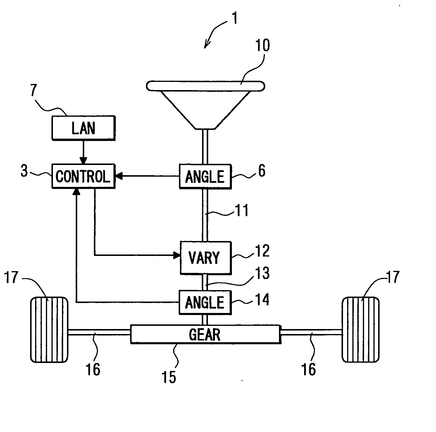
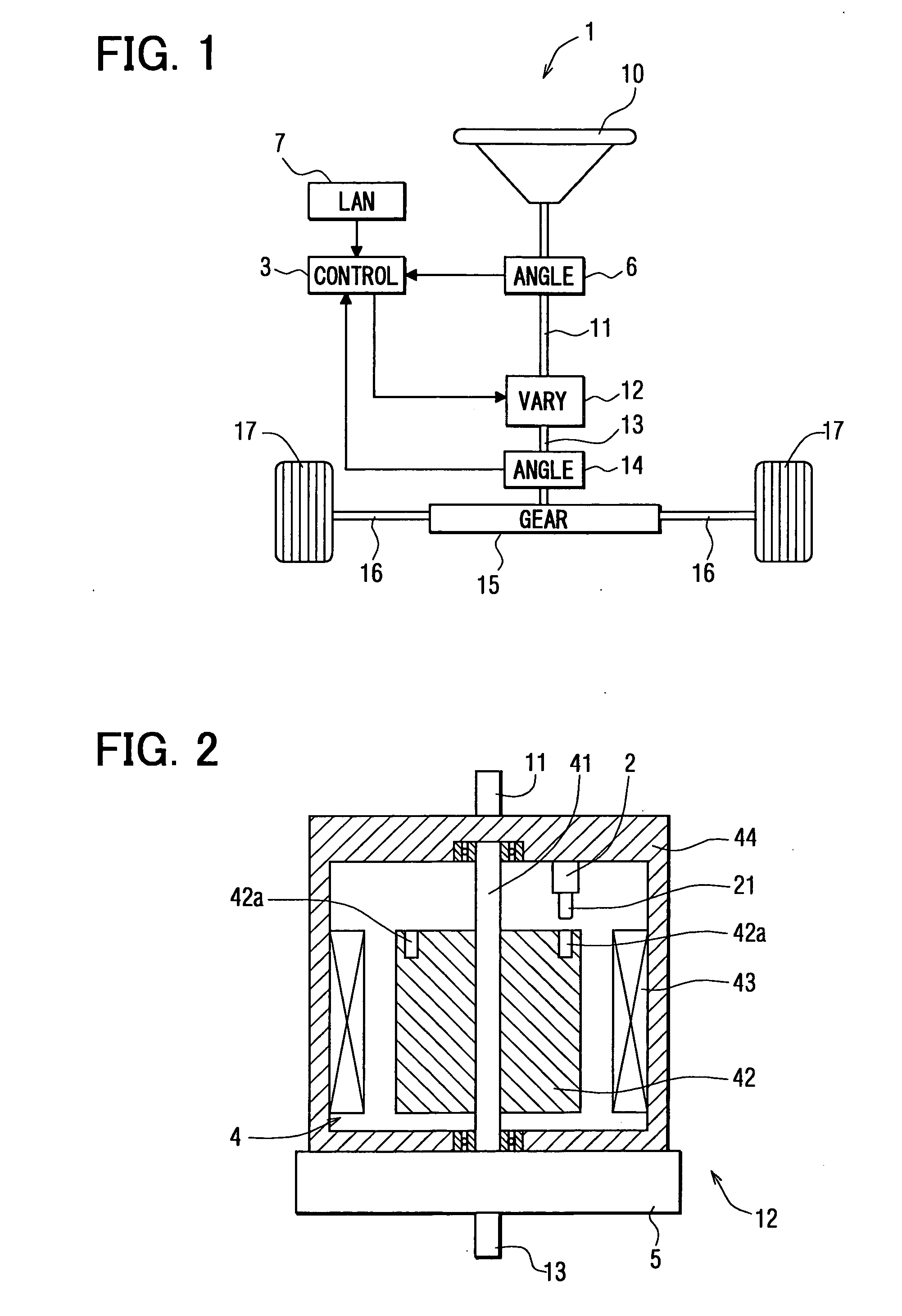
[0027] Referring first to FIG. 1, the electronic control system is a transfer-ratio varying steering system 1. A steering wheel 10 of a vehicle is connected to the upper end of an input shaft 11. The lower end of the input shaft 11 and the upper end of an output shaft 13 are connected to each other through a transfer-ratio varying mechanism 12. Furthermore, the lower end of the output shaft 13 is equipped with a pinion (not shown), and the pinion is engaged with a rack 16 in a steering gear box 15. Furthermore, an electromotive power steering device (not shown) is equipped in the steering gear box 15. Steered tire wheels 17 are connected to both ends of the rack 16 through tie rods and arms (not shown).
[0028] The input shaft 11 is equipped with a steering angle sensor 6 for detecting the steering angle of the steering wheel 10. The output shaft 13 is equipped with an output angle sensor 14 including a resolver for detecting the turning angle of the steered ...
second embodiment
[0058] (Second Embodiment)
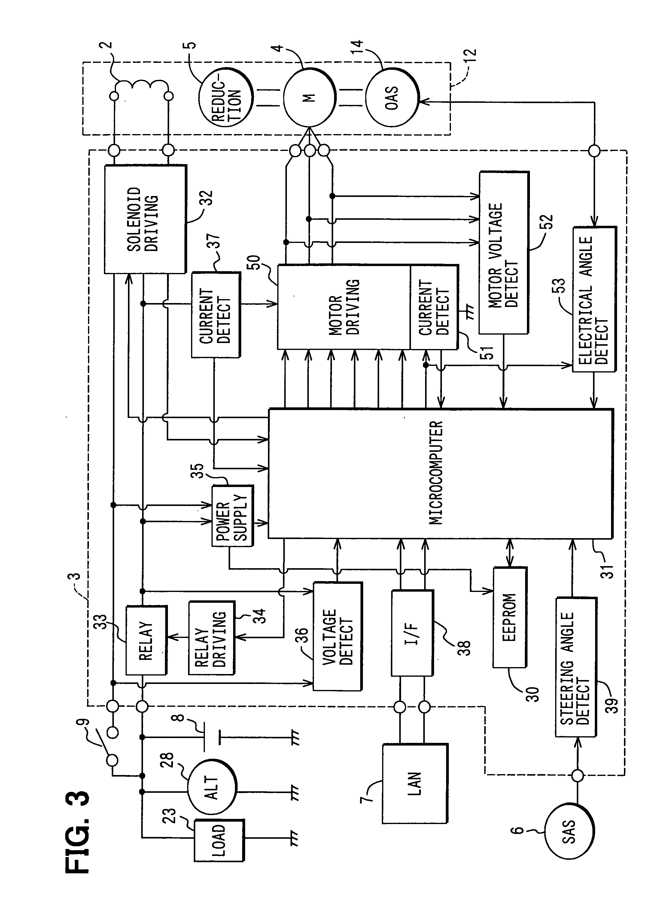
[0059] A second embodiment is shown in FIG. 6. A transistor T701 is connected between a resistor R204 of the motor driving circuit 50 (FIG. 3) and the ground, and the output terminal of the microcomputer 31 and the base terminal of the transistor T701 are connected to each other through a resistor R702.
[0060] When the power relay 33 is set to the ON-state, a control instruction is transmitted as a PWM signal from the microcomputer 31 to the transistor T701, and the transistor T701 is subjected to duty operation. The microcomputer 31 outputs to the relay driving circuit 34 an instruction for setting the power source relay 33 from the ON-state to the OFF-state, and also outputs to the transistor T701 a signal for setting the duty ratio for driving the transistor T701 to 100%, whereby the transistor T701 is set to the ON-state at all times and a discharge path extending from the resistor R204 through the transistor T701 to the ground is formed, so that the ch...
third embodiment
[0063] (Third Embodiment)
[0064] A third embodiment is shown in FIG. 7. The motor driving circuit 50 is wired to form a well-known three-phase bridge circuit. The circuit 50 includes fly-wheel diodes forming a bypass path of induced current caused by the switching of three-phase coils of U, V, W of the motor 4. If switching elements 301 to 306 are subjected to switching operation by using the rotational angle signal from the output angle sensor 14 and the PWM signal from a driving IC 314 which is based on an instruction from the microcomputer 31, a coil whose phase is associated with current supply can be selectively subjected to PWM current supply.
[0065] The switching elements 301, 302, 303 carry out switching operations of U-phase, V-phase and W-phase, respectively. Those switching elements are used as upper arm side switching elements. Furthermore, the switching elements 304, 305, 306 carry out the switching operations of U-phase, V-phase and W-phase, respectively. Those switchin...
PUM
 Abstract
Description
Claims
Application Information
 - R&D
- Intellectual Property
- Life Sciences
- Materials
- Tech Scout
- Unparalleled Data Quality
- Higher Quality Content
- 60% Fewer Hallucinations
Browse by: Latest US Patents, China's latest patents, Technical Efficacy Thesaurus, Application Domain, Technology Topic, Popular Technical Reports.
© 2025 PatSnap. All rights reserved.Legal|Privacy policy|Modern Slavery Act Transparency Statement|Sitemap|About US| Contact US: help@patsnap.com


