
Method and apparatus for implementing a MAC address pool for assignment to a virtual interface aggregate

a virtual interface and address pool technology, applied in the field of aggregation of physical links, can solve the problems of retransmission of packets, difficulty in removing physical interfaces from aggregates and reuse them as individual network interfaces, etc., and achieves the effect of fast and efficient manner

Inactive Publication Date: 2005-07-28
NETWORK APPLIANCE INC
View PDF17 Cites 39 Cited by
  • Summary
  • Abstract
  • Description
  • Claims
  • Application Information

AI Technical Summary

Benefits of technology

[0009] Advantageously, any modified address of the MAC address pool may be selected as the MAC address assigned to the aggregate. Removal of an underlying link from the aggregate is performed in a fast and efficient manner without disturbing the operation of the aggregate. That is, all network entities identify a static address with the aggregate, thereby enabling continued smooth flow of traffic to and from the aggregate. Moreover, an interface that is removed from the aggregate can be immediately reassigned its own MAC address without receiving spurious packets, i.e., packets that are destined for the aggregate. The novel modified MAC address pool may be extended for safe implementation in a multiprocessor environment by locking access to the pool.

Problems solved by technology

However, this method of assignment may make it difficult to remove a physical interface from the aggregate and reuse it as an individual network interface.
This procedure will unsettle the network for some time, possibly creating some problems.
To prevent transmitting incorrect information over the network, these packets must be discarded, which results in retransmission of the packets, delays in responding to requests from clients and inefficient usage of network bandwidth.
In addition, some clients may have the older MAC address identified as the address of the aggregate and this may take time to change.
This, in turn, results in periods of network inactivity, which is expensive.

Method used


Image

  • Method and apparatus for implementing a MAC address pool for assignment to a virtual interface aggregate
  • Method and apparatus for implementing a MAC address pool for assignment to a virtual interface aggregate
  • Method and apparatus for implementing a MAC address pool for assignment to a virtual interface aggregate

Examples


Embodiment Construction

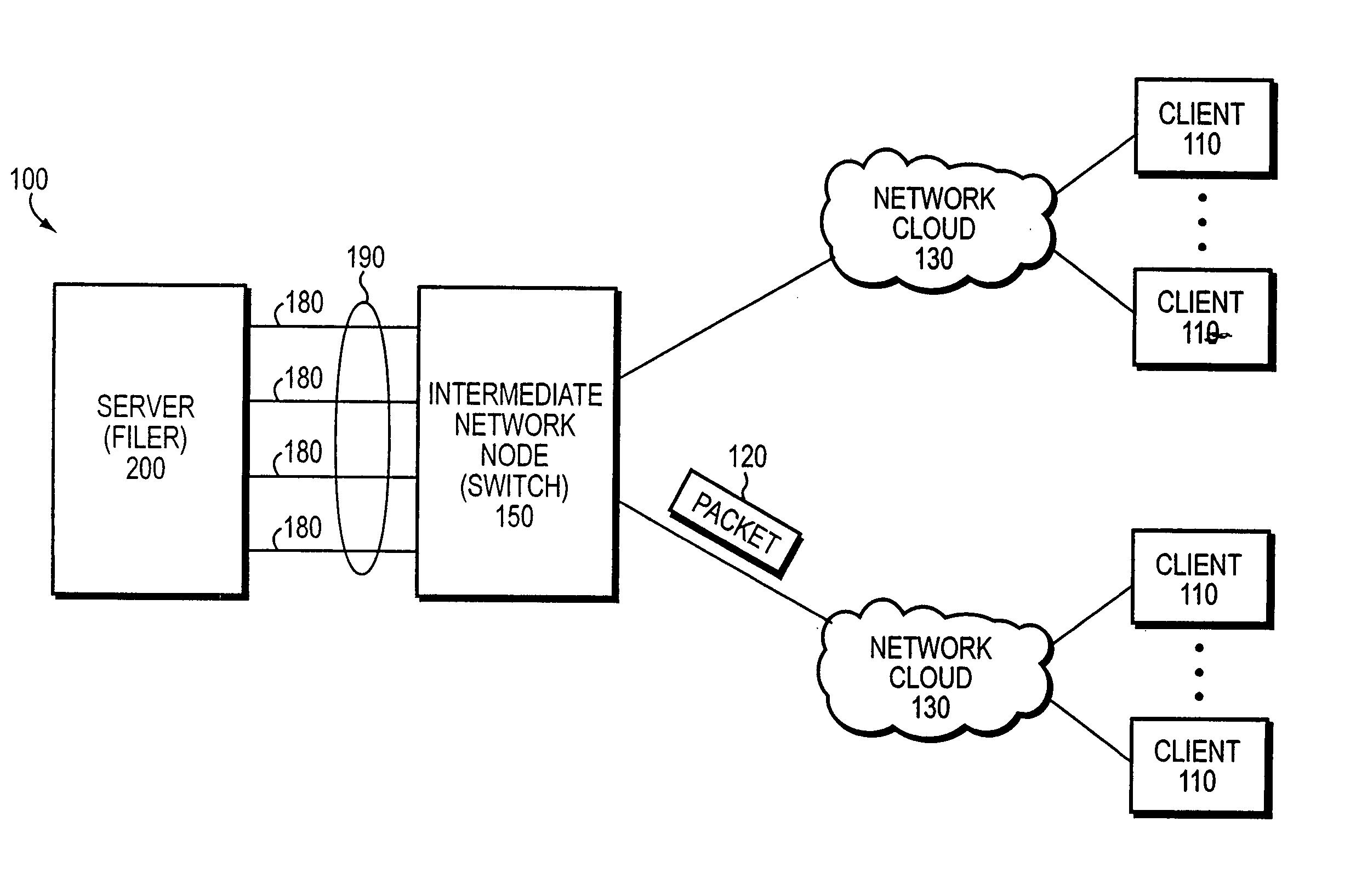
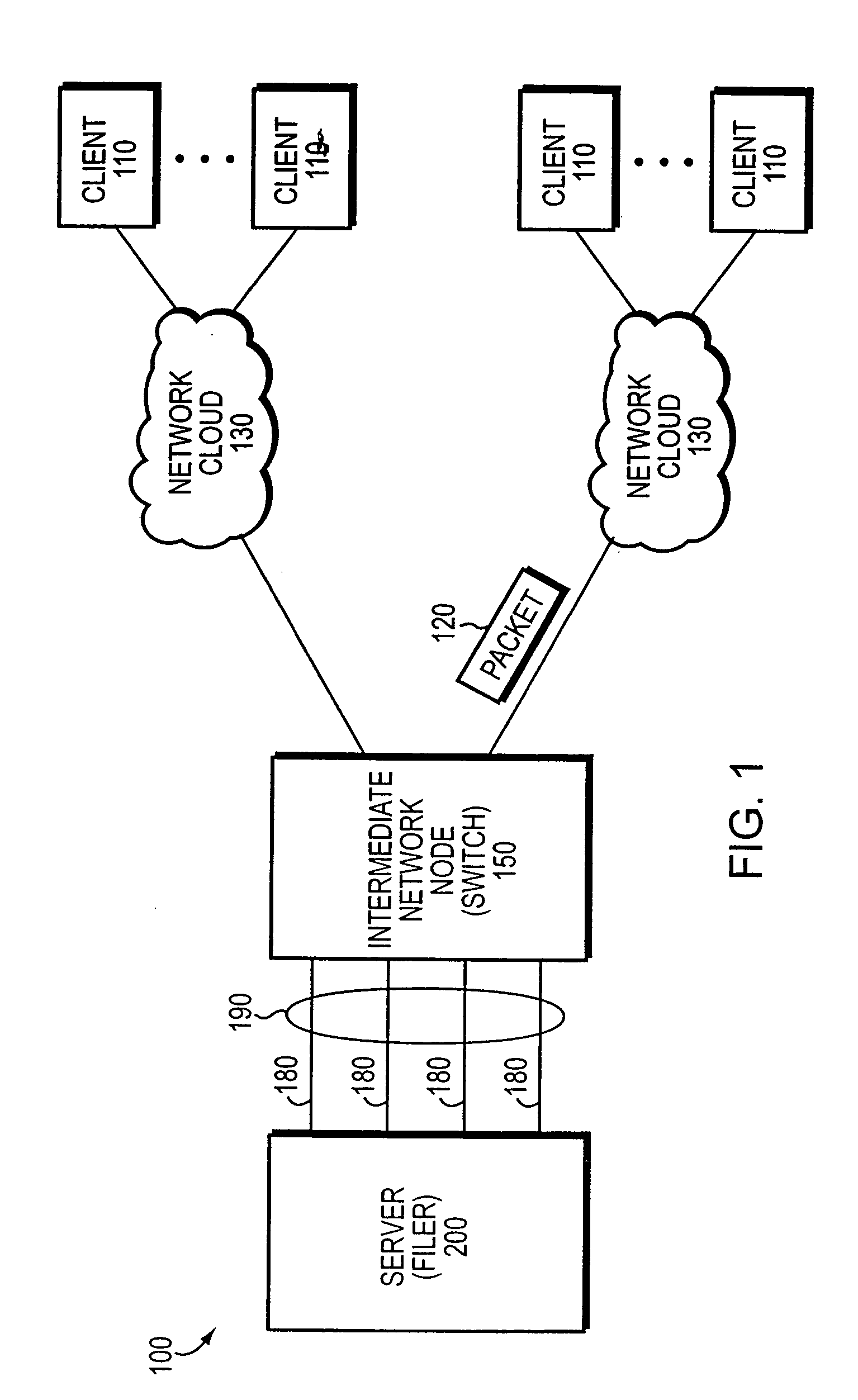
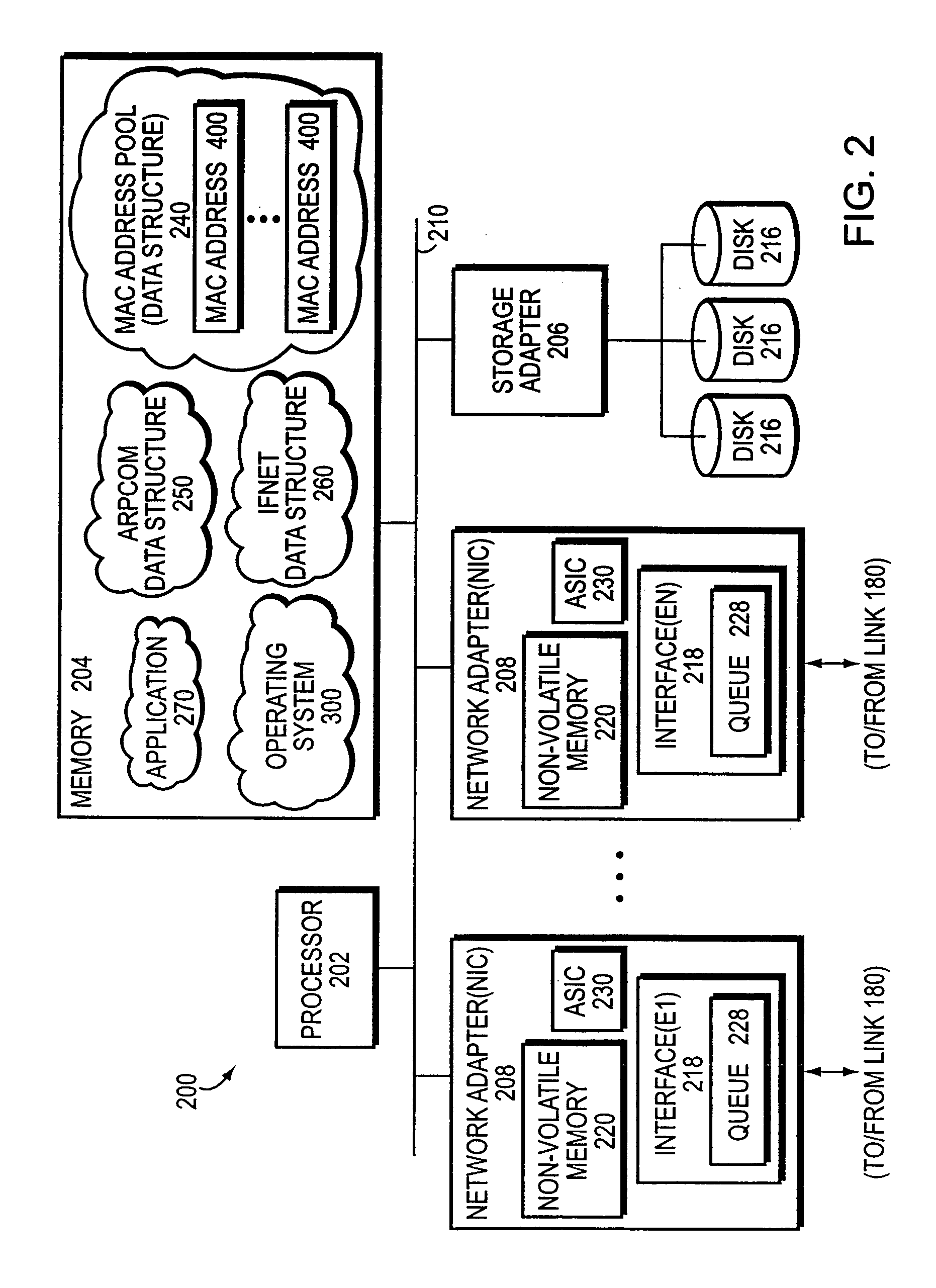
[0016]FIG. 1 is a schematic block diagram of a computer network 100 including a plurality of clients 110 and a server 200 that may be advantageously used with the present invention. The server is a special-purpose computer preferably configured as a network storage appliance or filer 200 that provides file service relating to the organization of information on storage devices, such as disks. The client 110 may be a general-purpose computer configured to execute applications, including file system protocols. Moreover, the client 110 may interact with the filer 200 in accordance with a client / server model of information delivery. That is, the client may request the services of the filer, and the filer may return the results of the services requested by the client, by exchanging packets 120 over the network 100. It will be understood to those skilled in the art that the inventive technique described herein may apply to any server capable of providing a service to any client in accordan...


PUM


Abstract

A method to implement an address pool is described. The method collects at least one address, the at least one address originally assigned as a unique address to at least one physical interface of a computer. Each originally assigned address is modified to be a plurality of modified addresses. The plurality of modified addresses is organized as an address pool. A selected modified address from the pool is assigned as a unique address for the pool. The selected modified address is used in contacting the computer in response to receiving a message addressed to an address of the pool.

Description

FIELD OF THE INVENTION [0001] The present invention relates to aggregation of physical links in a computer network and, more specifically, to a method and apparatus for configuring the aggregated physical links with a network address. BACKGROUND OF THE INVENTION [0002] Data communication in a computer network involves the exchange of data traffic between two or more entities interconnected by communication links. These entities are typically software programs executing on hardware computer platforms which, depending on their roles within the network, may serve as end nodes or intermediate network nodes. Examples of end nodes may include client and server computers coupled to the communication links, whereas the intermediate nodes may include routers and network switches that interconnect those links. The communication links may comprise a shared local area network (LAN) or point-to-point medium, an example of which is an Ethernet medium. [0003] A server is a special-purpose computer...

Claims


Application Information

Patent Timeline
IPC IPC(8): H04L29/06H04L29/08H04L29/12
CPCH04L29/12839H04L29/12952H04L61/6022Y02B60/33H04L69/14H04L69/324H04L61/6077Y02D30/50H04L2101/677H04L2101/622
Inventor GANGADHARAN, SUSHILKUMAR
Owner NETWORK APPLIANCE INC
Learn More