
Image reading apparatus

a technology of image reading and reading device, which is applied in the direction of electrical equipment, pictoral communication, etc., can solve the problems of difficult to reduce the memory space necessary for storing pixel data, and achieve the effect of reducing cost, large capacity and large memory

Inactive Publication Date: 2005-07-28
BROTHER KOGYO KK
View PDF4 Cites 6 Cited by
  • Summary
  • Abstract
  • Description
  • Claims
  • Application Information

AI Technical Summary

Benefits of technology

The present invention relates to an image reading apparatus that reduces the amount of memory needed to store pixel data. The apparatus includes an image sensor with multiple line sensors that output pixel signals. The pixel signals are converted into digital data and stored in a memory. However, only a limited number of pixels are needed for the application, such as for facsimile transmission or photocopying. The invention provides a data reduction rate setting device that determines the rate at which pixel data should be written into the memory. The reduction devices output only the necessary number of pixels based on the data reduction rate, reducing the amount of memory needed. This results in a more cost-effective and efficient image reading apparatus.

Problems solved by technology

However, by the reduction method disclosed in JP 9-180592, it is difficult to reduce memory space necessary for storing pixel data.

Method used


Image

  • Image reading apparatus
  • Image reading apparatus
  • Image reading apparatus

Examples


first embodiment

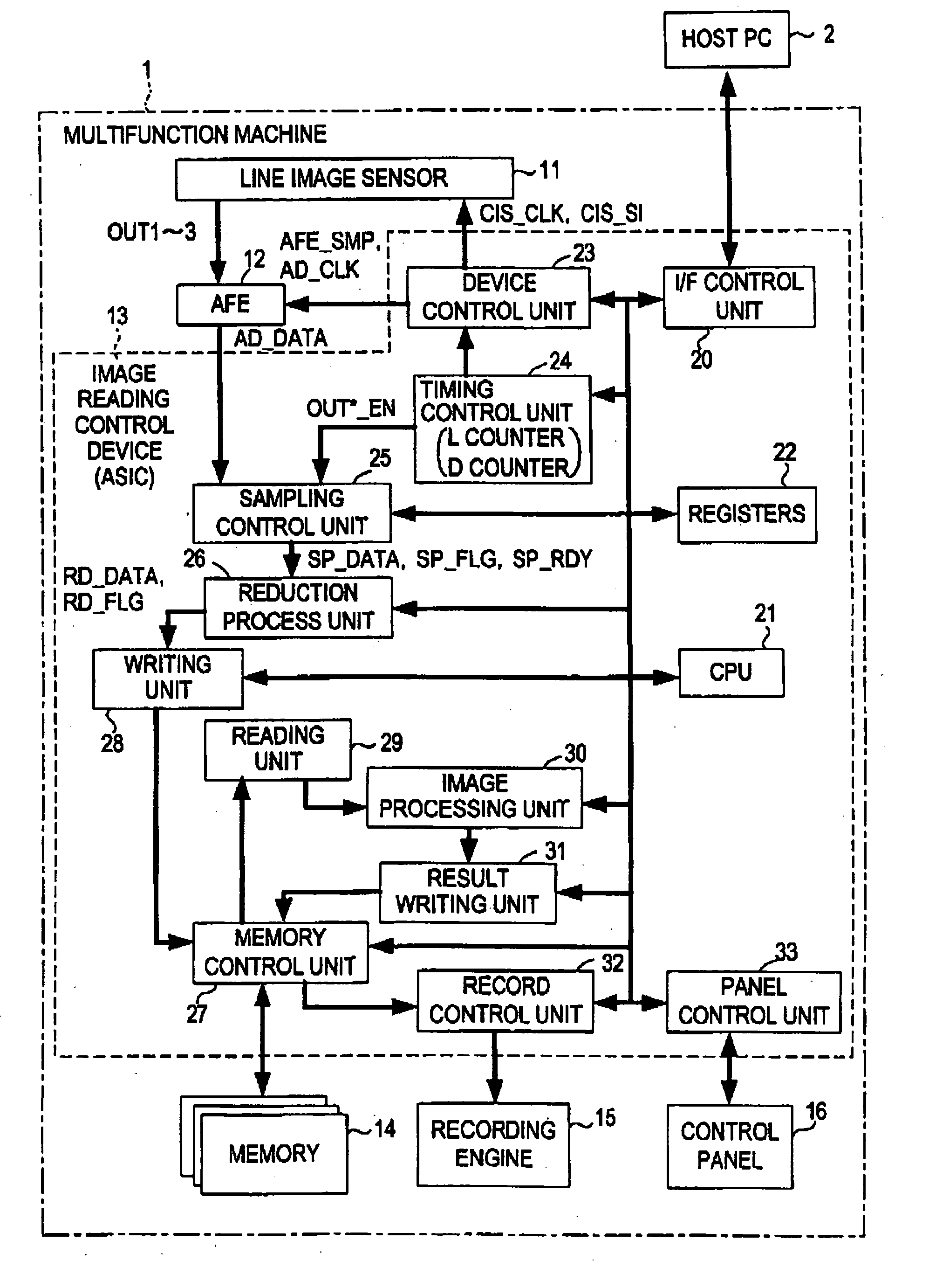
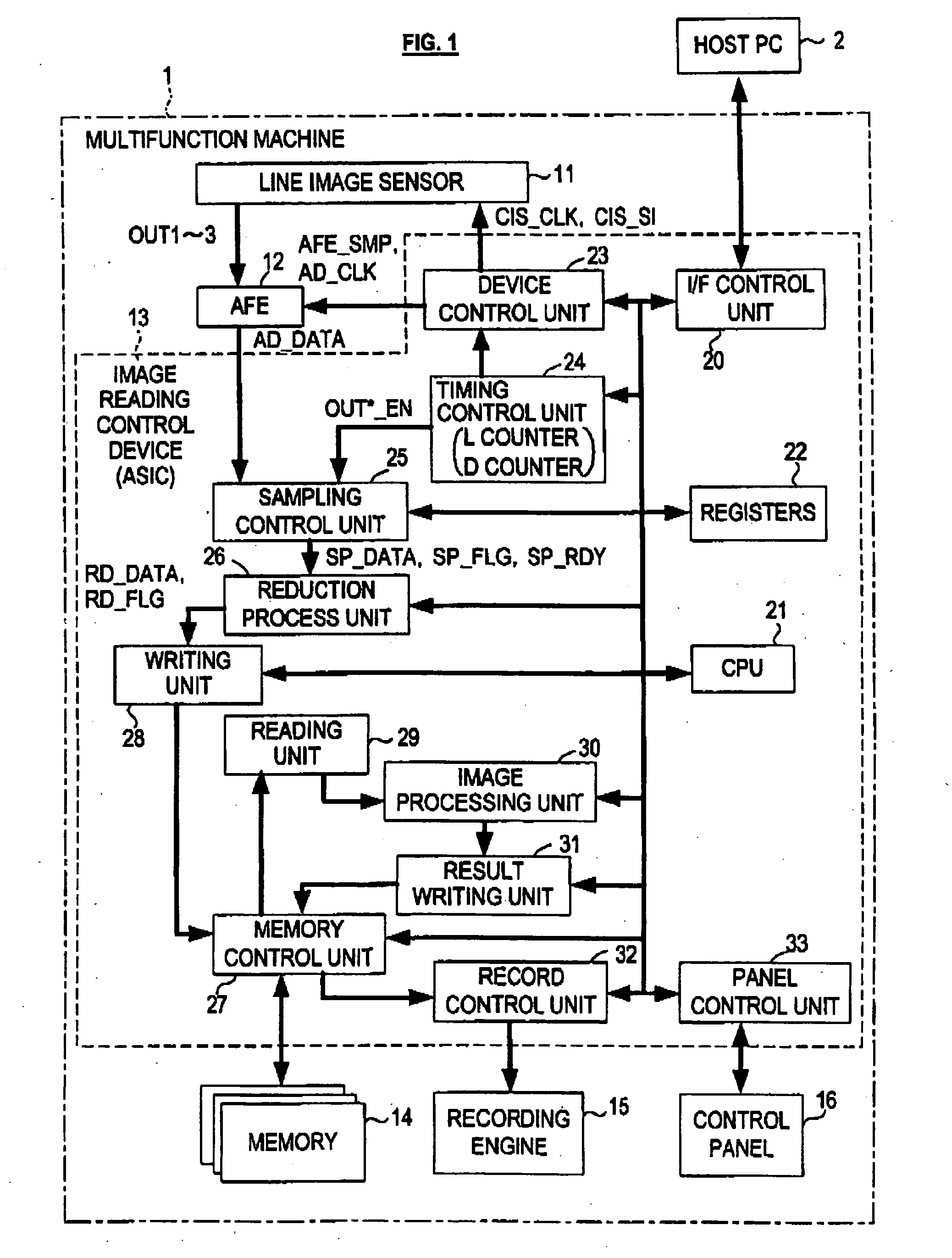
[0064] Referring to FIG. 1, a multifunction machine 1 of the present embodiment has at least following functions: one is a function as an image reading apparatus that reads out an image of an original with a line image sensor 11; and another is a function as a printer, that records the readout image or image data transmitted from a host computer (to be referred to as host PC) 2 on a recording medium such as a recording paper with a recording engine 15.

[0065] As shown in FIG. 1, the multifunction machine 1 of the present embodiment comprises: a line image sensor (CIS) 11 that reads out an image of an original; an analog front end (AFE) 12 that converts pixel signals of each pixel obtained from the line image sensor 11 into pixel data as digital data; an image reading control device 13 that conducts various processes for the pixel data from AFE 12; a memory 14 that temporally stores the pixel data gone through various processes conducted by the image reading control device 13; a reco...

second embodiment

[0139] In the multifunction machine 1 of the above-described embodiment, the reduction process for pixel signals taken from the sampling control unit 25 is conducted mainly by the ch1, ch2 and ch3 reduction process circuit 56, 57 and 58 respectively provided for each channel. These reduction process circuits 56 to 58 respectively comprise an adder. Every time pixel data of corresponding channel are taken, predetermined addition is conducted, and pixel data are skipped when a carry bit does not occur from the addition result.

[0140] Contrastingly, in the present embodiment, rate of data reduction is fixed to a specific rate. Every time pixel data are inputted, a value of a counter is incremented. When the value of the counter reaches preset count value for skipping the pixel data inputted at that time are skipped. Therefore, except for the point that rate of data reduction is fixed (to ⅚ in the present embodiment), and the structure of the reduction process unit 26, the constitution ...


PUM


Abstract

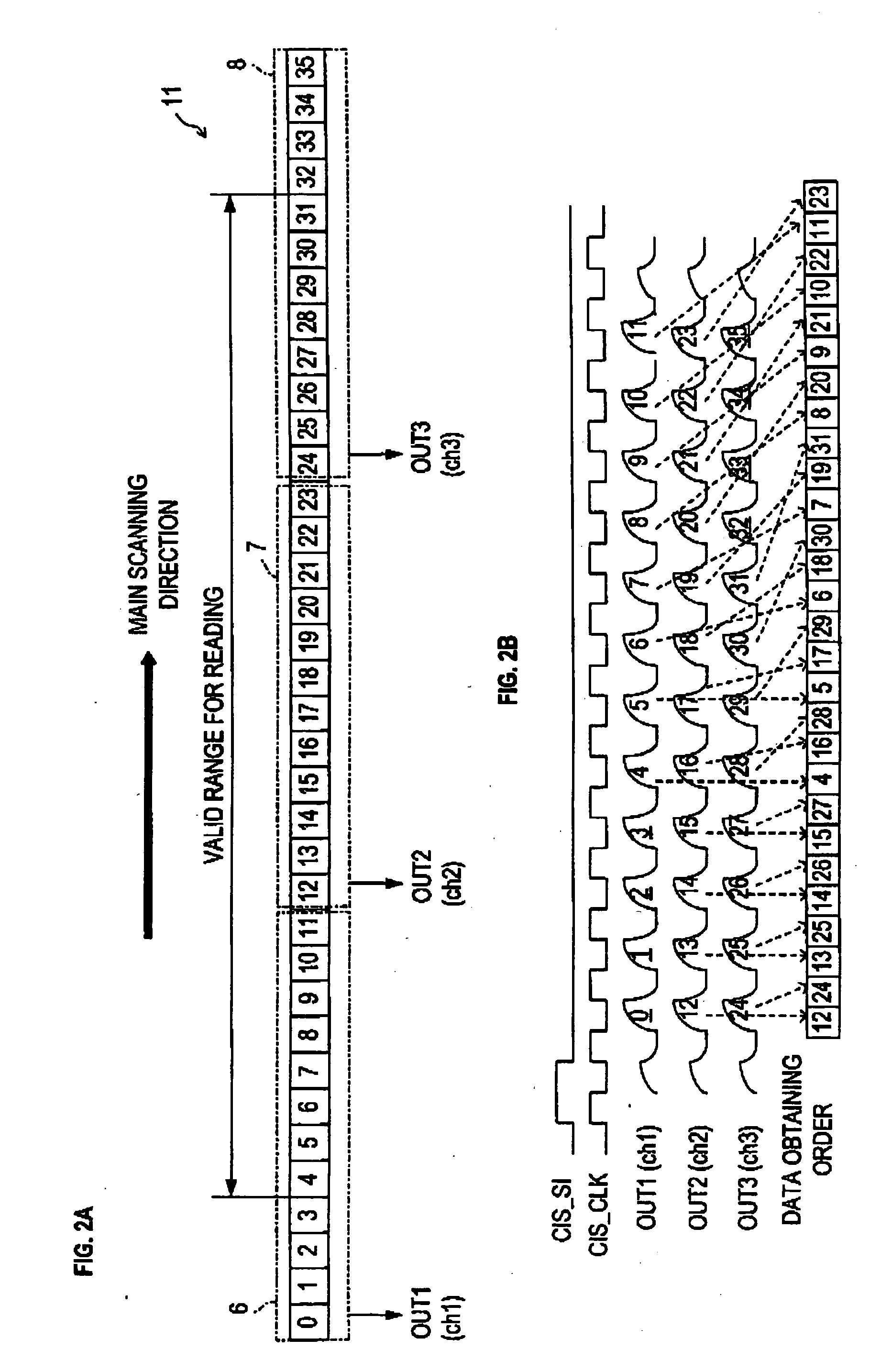
The image reading apparatus comprising an image sensor with plurality of reading devices one-dimensionally aligned in a main scanning direction allows reducing memory space necessary for image reduction process. Pixel signals in each channel read by a line image sensor are converted into pixel data in AFE, valid pixel data are captured therefrom, and then inputted into a reduction process unit. The reduction process unit skips pixel data sequentially inputted therein with predetermined intervals based on preset data reduction rate. Subsequently, pixel data after reduction process, that is only unskipped pixel data, are written into a memory via writing unit and memory control unit.

Description

BACKGROUND OF THE INVENTION [0001] (1) Field of the Invention [0002] This invention relates to an image reading apparatus that reads an image by using an image sensor with light receivers aligned one dimensionally. [0003] (2) Background Art [0004] An image reading apparatus that reads out an image from an original by using an image sensor with one-dimensionally-aligned light receivers has been known. This type of image reading apparatus is generally installed in a photo copier, facsimile, scanner, or a multifunction machine wherein functions of these devices are combined in one machine. [0005] For an image sensor an image sensor with CCD (Charge Coupled Devices) method, or CIS (Contact Image Sensor) are, for example, known. Amongst theses image sensors, especially CIS are often used, since they does not require complex optical systems for size reduction of a subject image while this system is necessary for an image sensor with CCD method to read out an image, and consequently size o...

Claims


Application Information

Patent Timeline
Patent Type & Authority Applications(United States)
IPC IPC(8): H04N1/19H04N1/393H04N1/40
CPCH04N1/40068
Inventor TAKAHASHI, OSAMU
Owner BROTHER KOGYO KK
Learn More