Exposure apparatus and purging method for the same

a technology of purging method and exposure apparatus, which is applied in the field of exposure apparatus and purging method for the same, can solve the problems of only a small amount of impurities left in the purged space, the non-transparent “blur” of glass materials, and the influence of only a small amount of impurities, etc., and achieve the effects of increasing the molecular amount of emission gas, reducing the flow rate, and increasing the flow ra

Inactive Publication Date: 2005-07-28
CANON KK
View PDF2 Cites 0 Cited by
  • Summary
  • Abstract
  • Description
  • Claims
  • Application Information

AI Technical Summary

Benefits of technology

[0012] It has been desired to quickly exhaust an emission gas source of internal components, while, keeping low, the speed of deterioration of optical components due to the gas emitted from the inside components or materials within a purge space.
[0014] With the provision of the switching means, between the exposure period and the non-exposure period, the amount of purge gas supply can be controlled separately. Thus, for example, the purge gas supply amount may be increased during the non-exposure period, to increase the flow rate of the purge gas passing along the inside component surface thereby to increase the molecular amount of emission gas to be removed from the component surface. Since the amount of emission gas (impurities) to be removed increases, the emission gas source can be exhausted in a shorter time period. On the other hand, during the exposure process, the purge gas flow rate may be decreased to a necessary and sufficient level. Because of the decreased flow rate, an absolute amount of emission gas from the components inside the purge area decreases, and the amount of impurities passing along the optical component surface per unit time decreases. Thus, adhesion of impurities onto the optical components during the exposure process can be minimized.

Problems solved by technology

This results in an inconvenience that the product of the reaction (blurring matters) adheres to glass materials to cause non-transparent “blur” of the glass materials.
However, with increases in the repetition frequency of the laser emission, resulting from a recent wavelength-shortening of lasers, the illuminance has been increased and, therefore, the influence of only a small amount of impurities left in the purged space has become a problem.
However, even if the entry of outside gas is suppressed and high purity of supplied purge gas is kept, it is difficult to completely avoid a small amount of emission gas from components used in the purge space.
However, to completely remove them is difficult to achieve.
These mechanisms may include components such as resins, unsuitable for heating treatment.
Although the amount of emission gas from these components is small in terms of absolute quantity, due to recent shortening in wavelength of the exposure apparatus or increasing illuminance, over a long time period, the impurities contained in a small amount of gas may adhere to optical components to decrease the light transmissivity or reflectivity.
By increasing the flow rate, the molecular weight of the emission gas to be removed from the component surface increases, so that fast exhaustion of the emission gas source is expected.
Therefore, if the exposure process is carried out in this situation, more impurities adhere to the optical component, thus accelerating deterioration of transmissivity.

Method used


Image

  • Exposure apparatus and purging method for the same
  • Exposure apparatus and purging method for the same
  • Exposure apparatus and purging method for the same

Examples


first embodiment

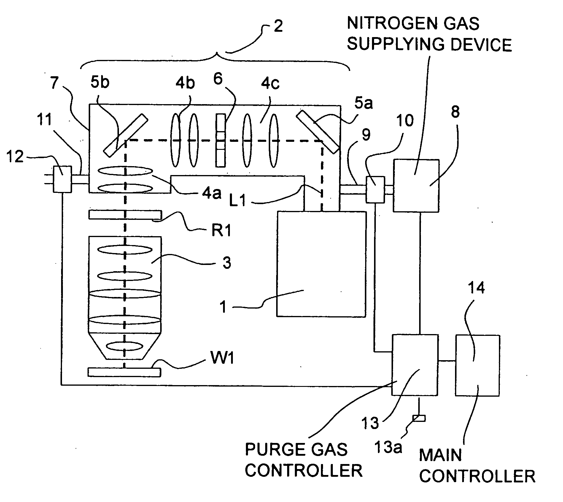
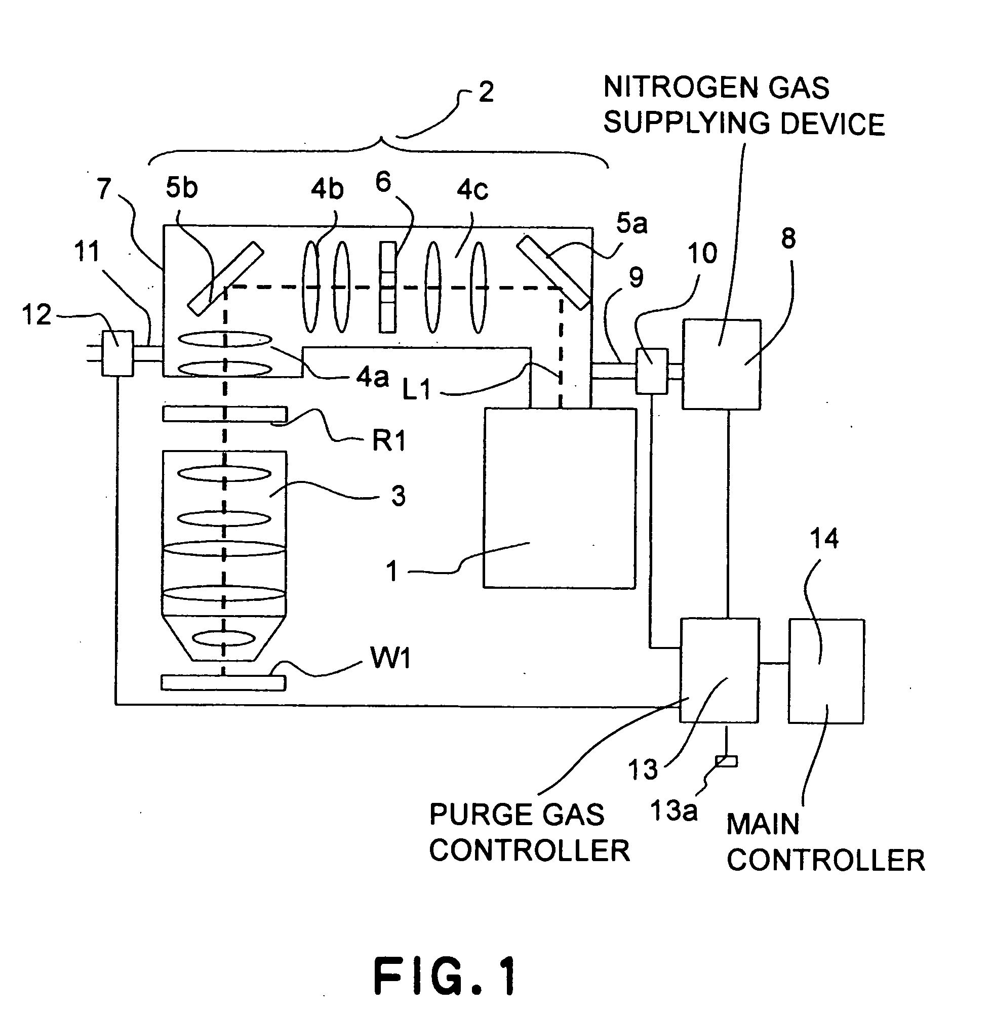
[0025]FIG. 1 illustrates an exposure apparatus according to a first embodiment of the present invention. In FIG. 1, denoted at 1 is a light source which comprises an excimer laser, and denoted at 2 is a light source lens system which is an optical system for shaping laser light L1, emitted from the light source 1, into a predetermined shape. Denoted at 3 is a projection lens system for imaging the laser light L1, shaped into a predetermined shape by the lens system 2, upon a wafer (substrate) W1 through a reticle R1.

[0026] The light source lens system 2 comprises optical elements such as different types of lens groups 4a, 4b and 4c and mirrors 5a and 5b, and it has a function for illuminating an illumination region on the reticle with the laser light L1 from the light source 1, with uniform illuminance. Also, it includes a sub-unit such as blind means 6 having a function for defining the shape (exposure view angle) of the illumination region on the reticle R1. The light source lens...

second embodiment

[0031]FIG. 3 shows an exposure apparatus according to a second embodiment of the present invention. The elements having the same functions as those of the FIG. 1 embodiment are denoted by like numerals, and a description thereof is omitted. The difference of this embodiment from the first embodiment will be described. In the first embodiment, in the exposure period and the non-exposure period, the nitrogen flow rate to be supplied is controlled to constant values set beforehand. In the second embodiment, on the other hand, gas analyzers 15 and 16 are connected to the nitrogen outlet port, and obtained values are fed back to calculate optimum nitrogen flow rates for the exposure period and the non-exposure period such that the flow rate is controlled with respect to these values.

[0032] Referring to FIG. 3, details will be explained. In FIG. 3, the basic structure is the same as that shown in FIG. 1. However, although in FIG. 1 the nitrogen passed through the casing 2 is exhausted fr...

third embodiment

[0034]FIG. 5 shows an exposure apparatus according to a third embodiment of the present invention. The elements having the same functions as those of the FIG. 3 embodiment are denoted by like numerals, and a description thereof is omitted. The difference of this embodiment from the second embodiment will be described. In the second embodiment, the light source lens system is purged by nitrogen. In the third embodiment, on the other hand, a projection lens system is purged by nitrogen. In the case of a projection lens system, as compared with a light source lens system, any change in inside pressure will have a large influence upon the image performance such as magnification or distortion. In consideration of this, a variable restriction 19 is provided in a gas exhaust line 11 to change the piping resistance at the nitrogen outlet port in accordance with the nitrogen supply amount, thereby preventing a change in inside pressure (gauge pressure) due to a change in flow rate, caused wh...


PUM

PropertyMeasurementUnit
emission wavelengthaaaaaaaaaa

Abstract

Disclosed is an exposure apparatus including an exposure light source, an optical system, a casing, a gas replacing system, and a control system. The optical system directs exposure light from the exposure light source to a photosensitive substrate. The casing accommodates therein at least one optical element of the optical system. The gas replacing system supplies a purge gas into the casing to replace a gas inside the casing with the purge gas. The control system controls the gas replacing system so as to increase a flow rate of the purge gas if a predetermined time elapses after an exposure is completed and before a next exposure starts.

Description

FIELD OF THE INVENTION AND RELATED ART [0001] This invention relates to an exposure apparatus and a purging method for the same, suitably applicable to an exposure apparatus for projecting a pattern of a mask onto a photosensitive substrate through a projection optical system, wherein short-wavelength laser light easily activating impurities and oxygen in an ambient environment is used as exposure light and wherein an exposure light passage inside the apparatus is replaced by an inactive gas. More particularly, the invention concerns a purge gas supply for supplying a purge gas such as inactive gas into a purge space of the exposure light passage, that accommodates optical components. [0002] The procedure of manufacturing semiconductor devices, constituted by very fine patterns such as LSI or VLSI, includes the use of a reduction projection exposure apparatus for projecting, in a reduced scale, a circuit pattern formed on a mask onto a substrate, coated with a photosensitive materia...

Claims


Application Information

Patent Timeline
Patent Type & Authority Applications(United States)
IPC IPC(8): G03B27/52G03F7/20H01L21/027
CPCG03B27/52G03F7/70933G03F7/70883
Inventor YAMAMOTO, SUMITADA
Owner CANON KK
Why Eureka
Try Eureka