
Switch

a technology of switch and movable member, which is applied in the field of switch, can solve the problems of forming incorrect signal paths, low response speed of movable members, vibration of elements, etc., and achieves the effects of improving signal propagation characteristics, low consumption power, and high speed respons

Inactive Publication Date: 2005-07-28
NAITO YASUYUKI +3
View PDF12 Cites 9 Cited by
  • Summary
  • Abstract
  • Description
  • Claims
  • Application Information

AI Technical Summary

Benefits of technology

"The present invention provides a high-performance switch with improved signal propagation, high-speed response, low power consumption, and low driving voltage. The switch includes an input port for inputting an external signal, a movable member, a first electrode for propagating the external signal, a first control power supply, a second electrode for blocking the external signal, and a second control power supply. The first control power supply generates a control signal to the first electrode, and the movable member is displaced by a driving force generated based on a potential difference between the movable member and the first electrode and a potential difference between the movable member and the second electrode. This makes it possible to realize a switch for signal propagation characteristic improvement, high-speed response, low power consumption, and low driving voltage."

Problems solved by technology

At this time, in case the voltage is abruptly applied or reduced to zero, a phenomenon called chattering takes place, resulting in vibration of the element.
This, however, poses a problem of low response speed for the movable member to return to a predetermined position.
Also, on a mechanical switch, in returning the movable member contacted with the electrode to a position where isolation is high not to cause a capacitance coupling of movable member and electrode, there is a problem of overshoot, i.e. the movable member is to displace beyond the predetermined position.
Where the overshoot of movable member is great, capacitance coupling possibly takes place on the electrode and movable member, as a signal propagation path, resulting in forming an incorrect signal path.
Accordingly, it is difficult to fix a beam having a length of several hundred μm only at one end.
However, where fixed at both ends, the substrate and beam materials, if different, cause a change of internal stress due to a difference in the thermal expansion coefficient between the materials, thereby changing the spring constant.
Based on a preparatory pulse voltage same as that at room temperature, it is impossible to prevent chattering.

Method used


Image

  • Switch
  • Switch
  • Switch

Examples


first exemplary embodiment

1. First Exemplary Embodiment

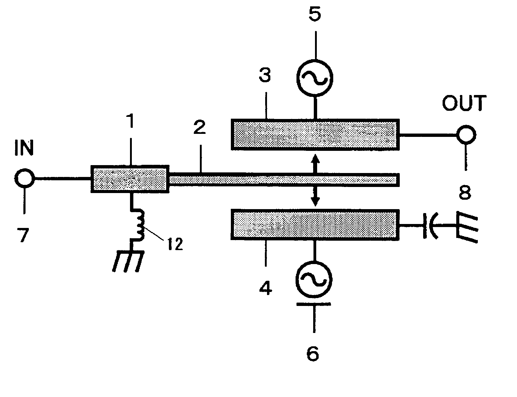
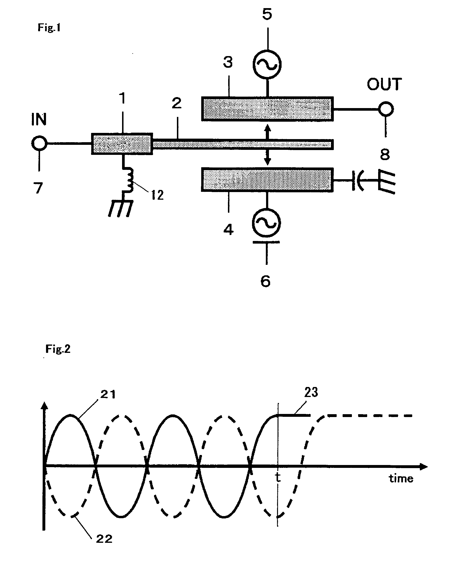
[0042]FIG. 1 depicts a plan view of a switch 1 in embodiment 1 of the present invention. An on-side electrode 3 is attached with an on-side control power supply 5 while an off-side electrode 4 is with an OFF-side control power supply 6. When the switch is on, a movable member 2 is to be attracted on the on-side electrode 3. The signal inputted through an input port 7 propagates to an output port 8 through the movable member 2 and on-side electrode 3. When the switch is off, the movable member 2 is to be attracted on the off-side electrode 4. The signal inputted through the input port 7 propagates to the ground through the movable member 2 and off-side electrode 4.

[0043]FIG. 2 shows a relationship between a control signal and a position of the movable member 2 in embodiment 1. FIG. 2 shows a control signal to be supplied to the on-side electrode 3 on one side. The on-side electrode 3 and off-side electrode 4 are provided with control signals 21 oppositel...

second exemplary embodiment

2. Second Exemplary Embodiment

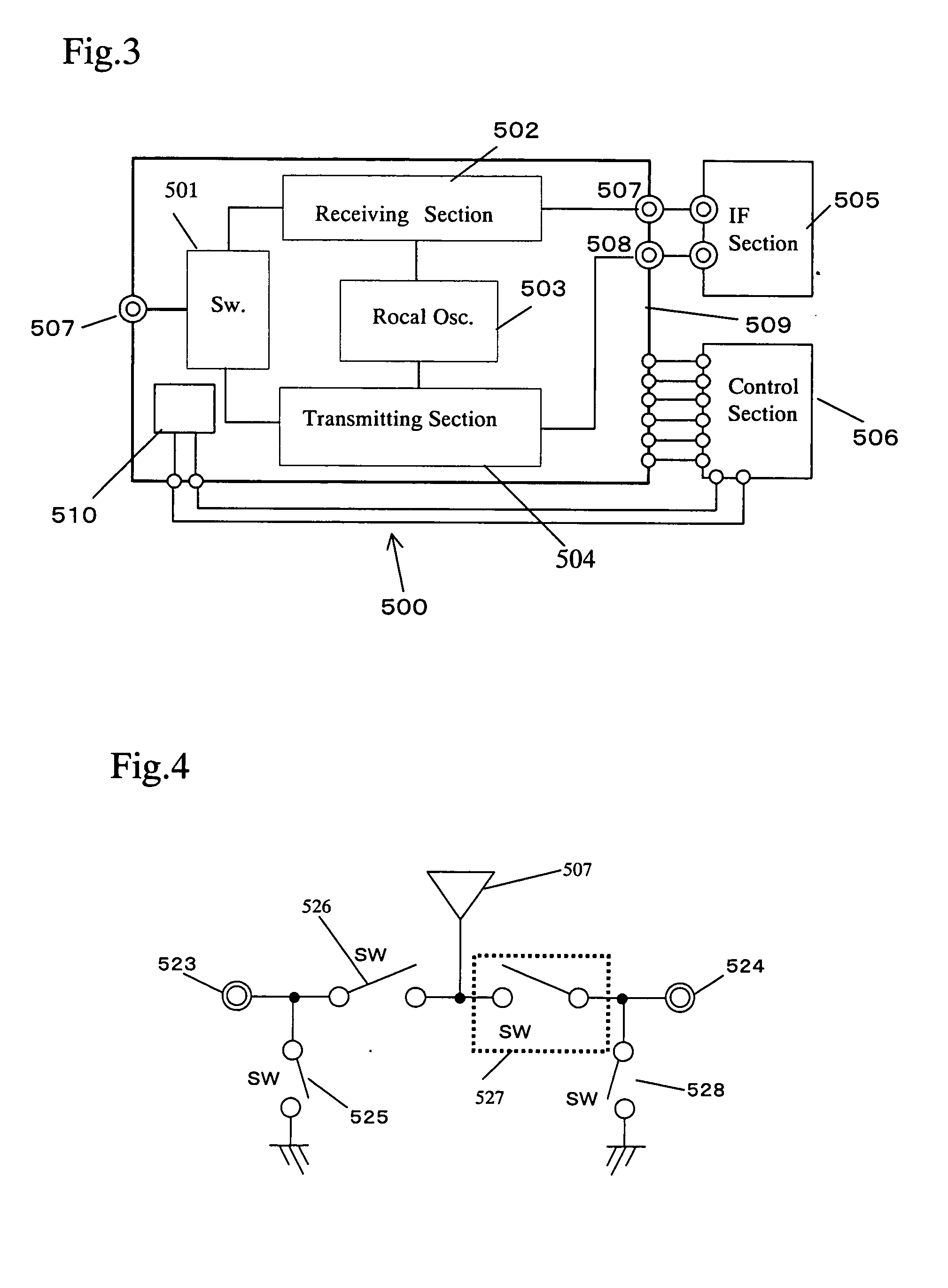
[0054]FIG. 3 shows a schematic configuration diagram of a switch in embodiment 2 of the invention. A transmitting / receiving section 500 of a radio transceiver is configured with a transmission / reception switching section 501, a receiving section 502, a local oscillator 503, a transmitting section 504, a control section 506, and an IF section 505. The transmission / reception switching section 501 is switched over to a receiving end and a transmission end, depending upon a control signal from the control section 506.

[0055] In the case of signal reception, an RF signal inputted at an antenna end 507 is inputted to the receiving section 502 through the transmission / reception switching section 501 where the signal is amplified and frequency-converted and thereafter outputted, at an IF terminal 507, to the IF section 505. In the case of sending a signal, operation is reverse to the above, i.e. the signal outputted from the IF section 505 is inputted to the tr...

third exemplary embodiment

3. Third Exemplary Embodiment

[0075] In using the switch, where the movable member is vibrated at all times, there is a problem that a signal is propagated to the output port with a period of a self-resonance of the movable member. As a switch this problem is solved, shown is a method that two switches are connected in series, for use as one switch.

[0076]FIG. 11 shows a plan view of a switch 1 in embodiment 3 of the invention. A switch 1a and a switch 1b are connected in series. The switch 1a has a movable member 2a, an on-side electrode 3a and an off-side electrode 4a. The on-side electrode 3a is connected with an on-side control power supply 5a while the off-side electrode 4a is connected with an off-side control power supply 6a. Similarly, the switch 1b has a movable member 2b, an on-side electrode 3b and an off-side electrode 4b. The on-side electrode 3b is connected with an on-side control power supply 5b while the off-side electrode 4b is connected with an off-side control pow...


PUM


Abstract

A switch for switching over a propagation path of external signal by contacting or non-contacting a movable member to or from an electrode. The switch comprises an input port for inputting an external signal, a movable member connected to the input port, a first electrode for propagating the external signal, a first control power supply connected to the first electrode and for generating a control signal, a second electrode for blocking the external signal, and a second control power supply connected to the second electrode and for generating a control signal. The first control power supply provides a control signal to the first electrode. The movable member is displaced by a driving force generated based on a potential difference between the movable member and first electrode and a potential difference between the movable member and second electrode, thereby being contacted to the first or second electrode.

Description

FIELD OF THE INVENTION [0001] This invention relates to a switch, for use on an electronic circuit or the like, adapted for switching over a propagation path for an external signal by attracting or repelling the movable member to or from the electrode. BACKGROUND OF THE INVENTION [0002] The conventional RF-MEMS switch is a mechanical switch having movable members in a membrane or rod form supported at both ends or in a cantilever, so that by placing them into or out of contact with the electrodes, signal propagation path can be switched over. Although the power sources for driving the membrane or movable member, in many cases, use those based on electrostatic force, there are released ones using magnetic force. [0003] As a micro-fabricated switch in a size around 100 μm, there is known one described in IEEE Microwave and Wireless Components letters, Vol. 11 No 8, August 2001 p 334. This switch forms a signal line for radio-signal transmission over a membrane, to provide a control el...

Claims


Application Information

Patent Timeline
Patent Type & Authority Applications(United States)
IPC IPC(8): H01H47/22H01H53/02B81B3/00H01H59/00H01P1/10H01P1/12
CPCH01P1/127H01H59/0009
Inventor NAITO, YASUYUKINAKANISHI, YOSHITOSHIMIZU, NORISATONAKAMURA, KUNIHIKO
Owner NAITO YASUYUKI
Learn More