
Hinged door safety device

Inactive Publication Date: 2005-07-28
MISKIN MICHAEL
View PDF8 Cites 12 Cited by
  • Summary
  • Abstract
  • Description
  • Claims
  • Application Information

AI Technical Summary

Benefits of technology

[0005] A primary object of the present invention is to provide a portable, inexpensive and effective safety device for hinged doors that can be readily installed to an existing door.
[0006] Another object of the present invention is to provide a simple safety device for hinged doors that can address the aforementioned problems commonly associated with hinged doors.
[0007] A further object of the present invention is to provide a portable safety device for hinged doors that can be easily and inexpensively manufactured and can be used on a first door and re-used on other doors.

Problems solved by technology

On many occasions, a child injures itself severely by insertion of its fingers or other body parts into the open gap created on the front face of a bi-fold door or the gap created between a hinged door and the fixed door frame.
Occasionally, children may accidentally close a door on the fingers or other body parts of another child while at play.
This is frequently an undesirable event.
Some of these devices are not portable, and are cumbersome to make, transport and install.
Also, these devices are not easily relocated from door to door without the risk of defacing the doors from hardware or adhesive marks if they were to be removed.

Method used


Image

  • Hinged door safety device
  • Hinged door safety device
  • Hinged door safety device

Examples


Embodiment Construction

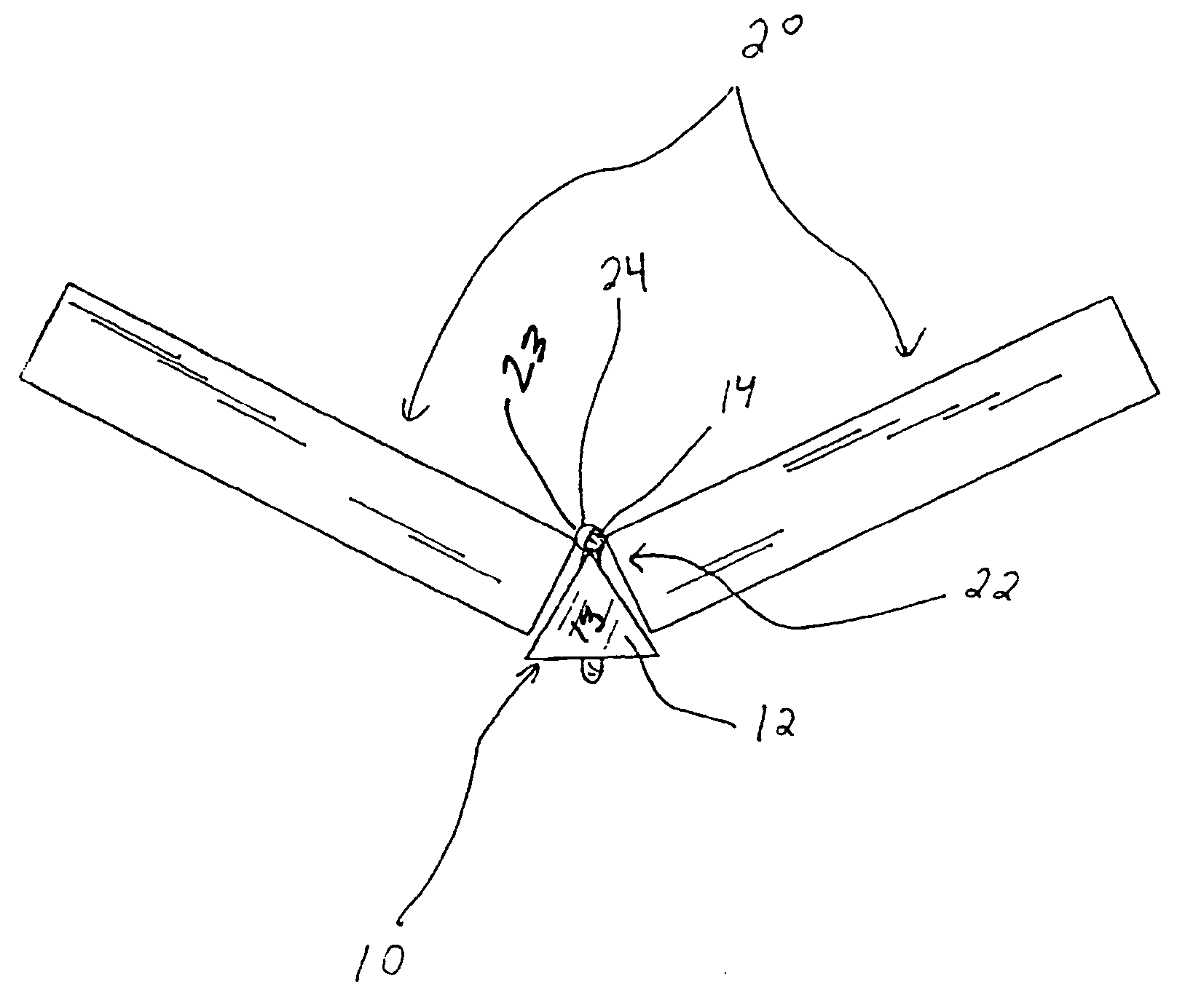
[0027]FIG. 1 disclose a safety device 10 for use with a door panel hinged to another door element such as another door or to a door frame or jamb for relative swinging motion of the door panel. FIGS. 2 and 3 disclose the device 10 in use with a bi-folding door where like door panels 20 comprise both elements of the hinged assembly.

[0028]FIGS. 1-3 disclose that the safety device 10 includes a block 12 sized and configured to insert into a triangular space 22 formed between the door panels 20 when the door panels are in a non-closed position. A ligature in the form of a resilient strap 14 having two segments 14a, 14b each having free ends secures the block 12 to the door assembly by looping around a hinge 24. A connector 18 of conventional buckle type (although any conventional connector appears to be appropriate e.g. hook and loop (e.g. Velcro®), snap, or the like) secures the free ends of the straps 14a, 14b together to secure the loop. The free ends could also be simply knotted to...


PUM


Abstract

A safety device for use with a door panel hinged to another door element such as another door or to a door frame or jamb for relative swinging motion of the door panel. The device has a block sized and configured to insert into a triangular space formed between a door panel and another door element to which the door panel is hinged when the door panel is in a non-closed position, but to resist traverse through a through-gap between the door panel and the other door element to which it is hinged. A keeper is connected to the block, the keeper having a first portion thereof being sized to fit through the through-gap, and a second portion adapted to resist traverse through the through-gap when in normal operation of the door after installation of the safety device. A first portion of the keeper is resilient, thus permitting a distance between the second portion of the keeper and the block to be varied without disconnecting the block from the keeper while providing a bias force to urge the block into the triangular space when the door is in a non-closed position. The first portion of the keeper is sized to permit a distance between the block and the second portion of the keeper to be sufficient to permit the block to be completely out of the triangular space while still being connected to the second portion of the keeper.

Description

CROSS REFERENCE TO RELATED APPLICATIONS [0001] This application claims the benefit of U.S. Ser. No. 60 / 531,306 filed Dec. 19, 2003.TECHNICAL FIELD [0002] This invention relates to a safety device for hinged doors. More specifically, the invention relates to a blocking means that automatically enters into the open gap of a hinged door for preventing injuries to small children by precluding them from being able to close the doors once they are opened. BACKGROUND OF THE INVENTION [0003] On many occasions, a child injures itself severely by insertion of its fingers or other body parts into the open gap created on the front face of a bi-fold door or the gap created between a hinged door and the fixed door frame. Occasionally, children may accidentally close a door on the fingers or other body parts of another child while at play. It is also very common among children at play to shut themselves alone inside a room or closet by closing the hinged door. This is frequently an undesirable eve...

Claims


Application Information

Patent Timeline
IPC IPC(8): E05C17/02E06B7/36
CPCE05C17/025E05D11/00E05D15/264E05F5/02E06B7/36E05F2005/046E05Y2201/224E05Y2600/52E05Y2900/132E05F5/04Y10T292/1062
Inventor MISKIN, MICHAEL
Owner MISKIN MICHAEL
Learn More