
Receiving device, printer, and firmware update system

a technology of firmware update and receiving device, applied in error detection/correction, digital output to print unit, instruments, etc., can solve the problems of affecting the performance of original functions, and affecting the operation of receiving devices. , to achieve the effect of preventing the error of display errors in the receiving apparatus

Inactive Publication Date: 2005-07-21
PANASONIC CORP
View PDF6 Cites 78 Cited by
  • Summary
  • Abstract
  • Description
  • Claims
  • Application Information

AI Technical Summary

Benefits of technology

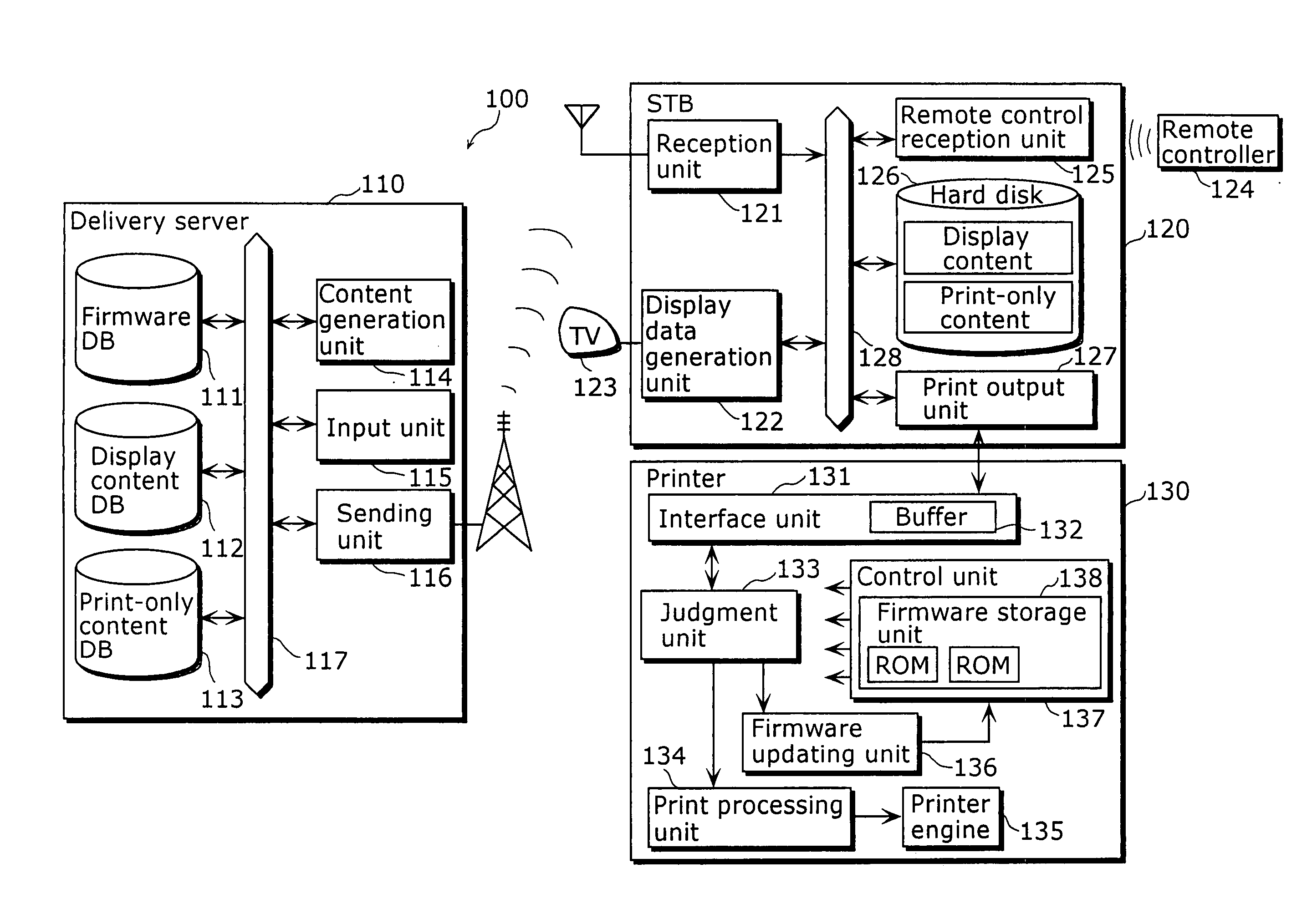
[0011] Thus, according to the receiving apparatus of the present invention, it is possible to display for guiding the user to update a firmware based on the display content, and also, the update data can be outputted to a printing apparatus in the same manner as in the case of normal print processing in accordance with the print command for the display content.
[0012] As a result, a firmware of the printer can be updated without adding, to the receiving apparatus, a new component for updating the firmware of the printing apparatus. Furthermore, the display errors occurred in the receiving apparatus can be prevented by allowing the receiving apparatus to print, but not to display, the firmware update data. The present invention is therefore of great significance.

Problems solved by technology

Here, it is undesirable to have the receiving apparatus perform the aforementioned picture data generating processing as it causes a decline in performance of original functions of the receiving apparatus such as a display of broadcast data while printing processing is under way.
Also, not all the receiving apparatuses are connected to the printing apparatus, which necessitates installing of a picture data generating processing module to the receiving apparatus that is not connected to the printing apparatus, which is a disadvantage in terms of cost.
However, an STB is by nature an apparatus to display the received broadcasting content on a TV monitor, therefore, it does not include a mechanism to update firmware of various peripheral apparatuses such as a printer.
There arises a problem of needing a significant system change in the STB in order to implement the system to update firmware of various peripheral apparatuses.

Method used


Image

  • Receiving device, printer, and firmware update system
  • Receiving device, printer, and firmware update system
  • Receiving device, printer, and firmware update system

Examples


first embodiment

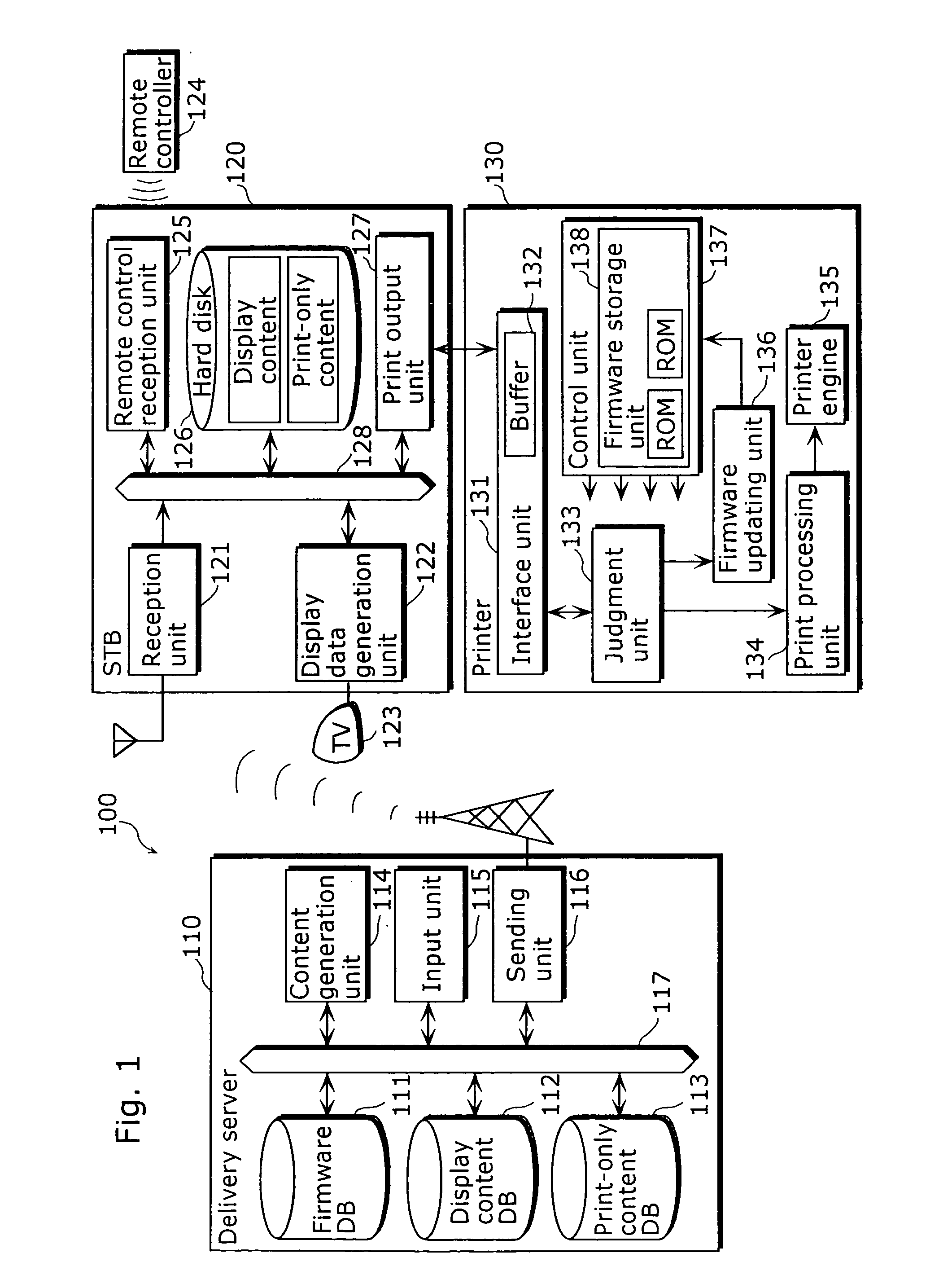
[0043]FIG. 1 is a functional block diagram showing a structure of a firmware updating system 100 according to the first embodiment of the present invention. The firmware updating system 100 is a system in which firmware update data for printing is sent from a delivery server at a broadcasting station as a print-only content which is not to be displayed on the TV and is received by a home STB, while a printer receives, from the STB, the firmware update data as print-only content and uses it to update its own firmware. The system includes a delivery server 110, an STB 120 and a printer 130. The print-only content is a content to be used exclusively for printing and cannot be displayed on a TV 123.

[0044] The delivery server 110, a server placed in the broadcasting station for TV broadcast, generates the broadcast content which allows the firmware update data to be a print-only content and sends the created broadcast content to each household through data broadcasting, for instance. Br...

second embodiment

[0078]FIG. 10 is a functional block diagram showing a structure of a firmware updating system 1000 according to the second embodiment of the present invention. The firmware updating system 1000 is a system in which the firmware update data for printing, which is one of the above-mentioned print-only contents is sent as an attached file to a broadcast e-mail that is described in a BML format from a delivery server placed in a broadcasting station for TV broadcast, a home STB which has received it saves the data once in a storage medium like a PC card so that a firmware of the printer is updated off-line. The system includes a delivery server 1010, an STB 1020 and a printer 1030. The same referential marks are put for the components which are as same as those composing the firmware updating system 100 described in the first embodiment, and the description is omitted as is already explained in the first embodiment.

[0079] The delivery server 1010 is a server, which generates a broadcas...

third embodiment

[0113] Next, the firmware updating system according to the third embodiment of the present invention is described. The present firmware updating system resembles to the first embodiment in the respect that the STB updates the firmware installed in the printer by outputting the firmware update data as a print-only content to the printer. However, the difference is that the STB does not receive the firmware update data as broadcast data but obtains the data on-demand from a specified website via the Internet.

[0114]FIG. 19 is a diagram showing the whole configuration of the firmware updating system 100a according to the present embodiment. The system 100a includes a firmware-providing site 140, that is, a portal site for providing services to update a firmware of the printer, is addition to the components included in the firmware updating system 100 described in the first embodiment.

[0115] Namely, the delivery server 110 and the printer 130 are as same as those described in the first...


PUM


Abstract

An STB (120), to which a printer (130) is connected, includes: a reception unit (121) to receive externally update data for updating a firmware of the printer and a display content which includes a description indicating that the update data is to be printed; a display data generation unit (122) to generate display data for displaying the display content on the TV (123); a remote control reception unit (125) to receive a print command for the display content; and a print output unit (127) to output, to the printer (130), the update data, as data to be printed, when the remote control reception unit (125) receives the print command.

Description

TECHNICAL FIELD [0001] The present invention relates to a firmware updating system for updating a firmware of a printer. BACKGROUND ART [0002] Recently, along with digitization of TV broadcast, various services became available to the users who watch the TV. Among these services, for example, in case of home shopping, e-mail delivery or timetable guide where rises a necessity to reconfirm the services and the information they received, there are many cases where it is convenient for the users to keep at hand a list of names of the products or the e-mails they received, after checking beforehand the details of desired information on the TV screen. Therefore, a system to receive information from a receiving apparatus such as a Set Top Box (STB) and a Digital TV (DTV) so as to print the received information with the printer which is directly connected to the receiving apparatus is useful. Under this system, the STB or the DTV is connected to the printer via an I / F such as an IEEE1394 b...

Claims


Application Information

Patent Timeline
IPC IPC(8): B41J29/38B41J5/30G06F3/12
CPCG06F8/65G06F3/1204G06F3/1288G06F3/123G06F3/1206
Inventor YAMAGUCHI, TAKEHITOMATSUNAGA, SHIGEKI
Owner PANASONIC CORP
Learn More