Electric motor comprising a stator cooling unit

a technology of electric motor and cooling unit, which is applied in the direction of dynamo-electric machines, lighting and heating apparatus, supports/enclosements/casings, etc., can solve the problems of air flow itself contributing to undesirable heat production to a considerable extent, and not only are complex sealing measures required, but also extensive safety measures to be taken into account. , to achieve the effect of reducing complexity

Inactive Publication Date: 2005-07-21
SIEMENS AG
View PDF14 Cites 13 Cited by
  • Summary
  • Abstract
  • Description
  • Claims
  • Application Information

AI Technical Summary

Benefits of technology

[0010] An object of the present invention is therefore to refine the machine with the features mentioned initially so as to allow effective cooling with relatively little complexity.
[0013] In comparison to air-cooled machines, this allows the air volume flow to be reduced by partial direct heat dissipation at the point where the heat losses are generated, via a thermosiphon. This results in a reduction in the development of heat that is produced by the air flow, which allows a further reduction in the air volume flow. This thus results in higher machine efficiency and savings in production costs, in particular for the winding and the laminated core of the stator.
[0019] The advantages associated with the refinement of the machine according to the invention are thus that the power range from which direct stator cooling is worthwhile can be reduced.
[0023] The stator parts to be cooled in the internal area advantageously make a large-area thermally conductive connection with the coolant. In this case, the stator parts to be cooled may also include laminates of a laminated core, in addition to a stator winding. Since heat is likewise produced in laminates such as these during operation, this can effectively be transferred to the coolant.
[0024] Furthermore, the stator of the machine may have cooling channels, which are integrated in the line system. Cooling channels such as these are particularly advantageous for the operation of the thermosiphon when the stator is arranged vertically (with the rotor axis running vertically), since any coolant vapor that is then produced can flow away well.
[0026] In addition, it may be regarded as particularly advantageous for a heating apparatus to be provided on or in the line system, in an area in which the coolant is at least largely in the liquid state. Specifically, a heating apparatus such as this makes it possible to reduce or compensate for undesirable pressure differences between the stator internal area, which is filled with the coolant, and the surrounding outside area when the machine is stationary (=shutdown in operation). This is because, when the machine is stationary, the stator generates virtually none of the heat that results in the heating of the coolant. This means that the internal area of the stator housing is cooled ever further owing to the cooling power which is introduced via the coolant as before, so that the pressure falls well below the environmental pressure. In conjunction with low external temperatures and material shrinkage, such a reduced pressure could result in leaks in the stator housing, via which air could be sucked in. This would lead to the boiling line of the coolant that is used being shifted, thus in the long time rendering the thermosiphon circuit ineffective. This risk can be precluded by using the special heating apparatus. This is because the heating apparatus makes it possible to prevent the stationary pressure falling below the environmental pressure in the stated area, preferably in an end-face area of the stator. The supply of heat results in the coolant being vaporized even when the machine is stationary. The corresponding vapor then condenses at cold points in that part of the thermosiphon line system which is formed by the stator internal area, where it thus heats the line system to a largely uniform temperature. This is associated with a pressure rise in the line system, corresponding to the boiling characteristic of the coolant that is used. In this case, the heating power can advantageously be regulated via a pressure sensor, so as to set a pressure at least equal to the environmental pressure in the line system. Since virtually no power losses occur during a shutdown in operation, the heating apparatus has to compensate only for the convective losses via the stator housing to the environment.

Problems solved by technology

In this case, however, the air flow itself contributes to undesirable heat being produced to a considerable extent, as a consequence of friction losses in the channels.
In this case, not only are complex sealing measures required, but extensive safety measures also have to be taken into account.

Method used


Image

  • Electric motor comprising a stator cooling unit
  • Electric motor comprising a stator cooling unit
  • Electric motor comprising a stator cooling unit

Examples


Embodiment Construction

[0032] Reference will now be made in detail to the preferred embodiments of the present invention, examples of which are illustrated in the accompanying drawings, wherein like reference numerals refer to like elements throughout.

[0033] The electrical machine according to the invention is based on machines which are known per se in the higher power range, such as generators. Parts which are not illustrated are generally known. Only those parts of the machines which are significant to the invention are shown in the figures.

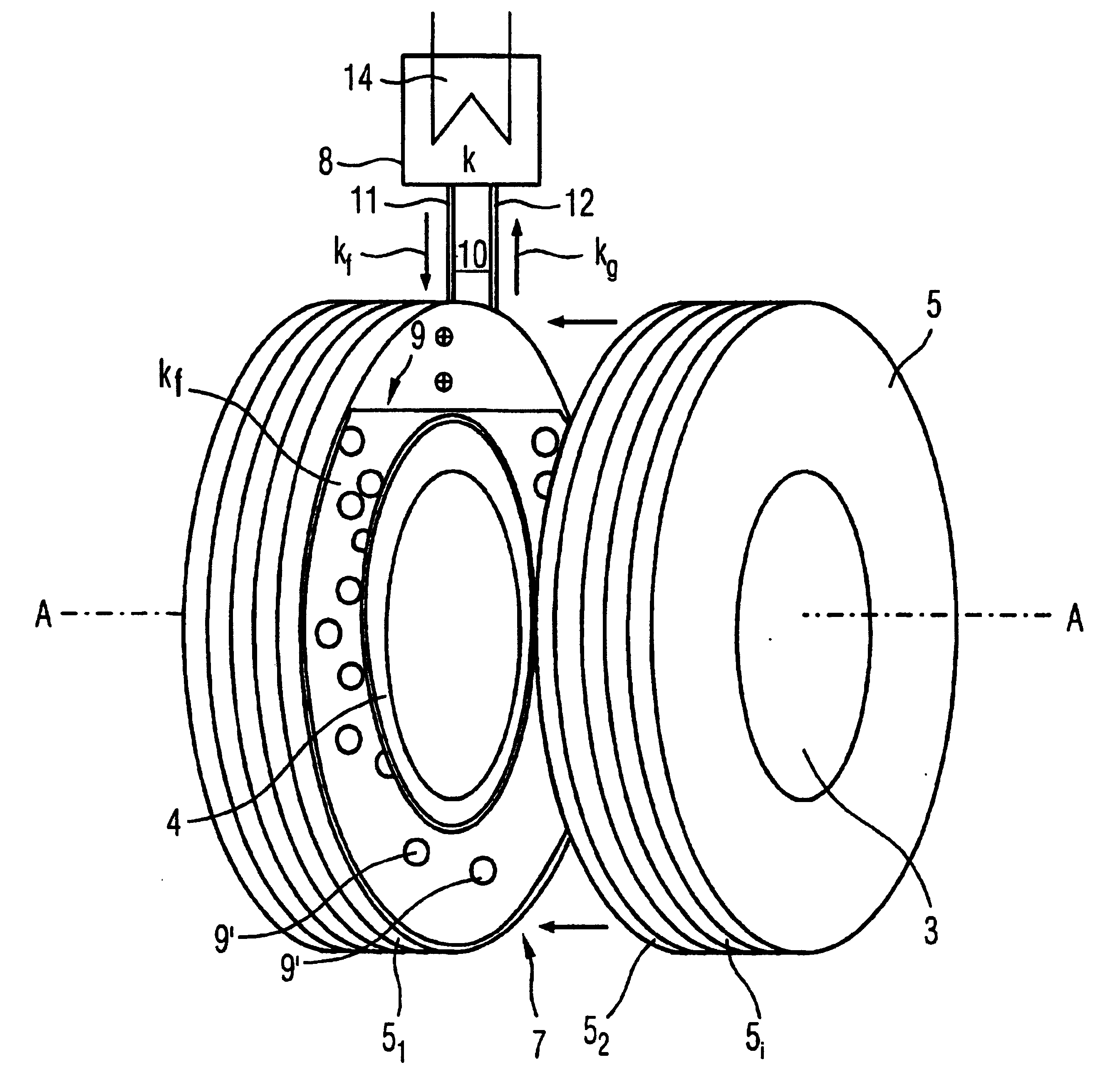
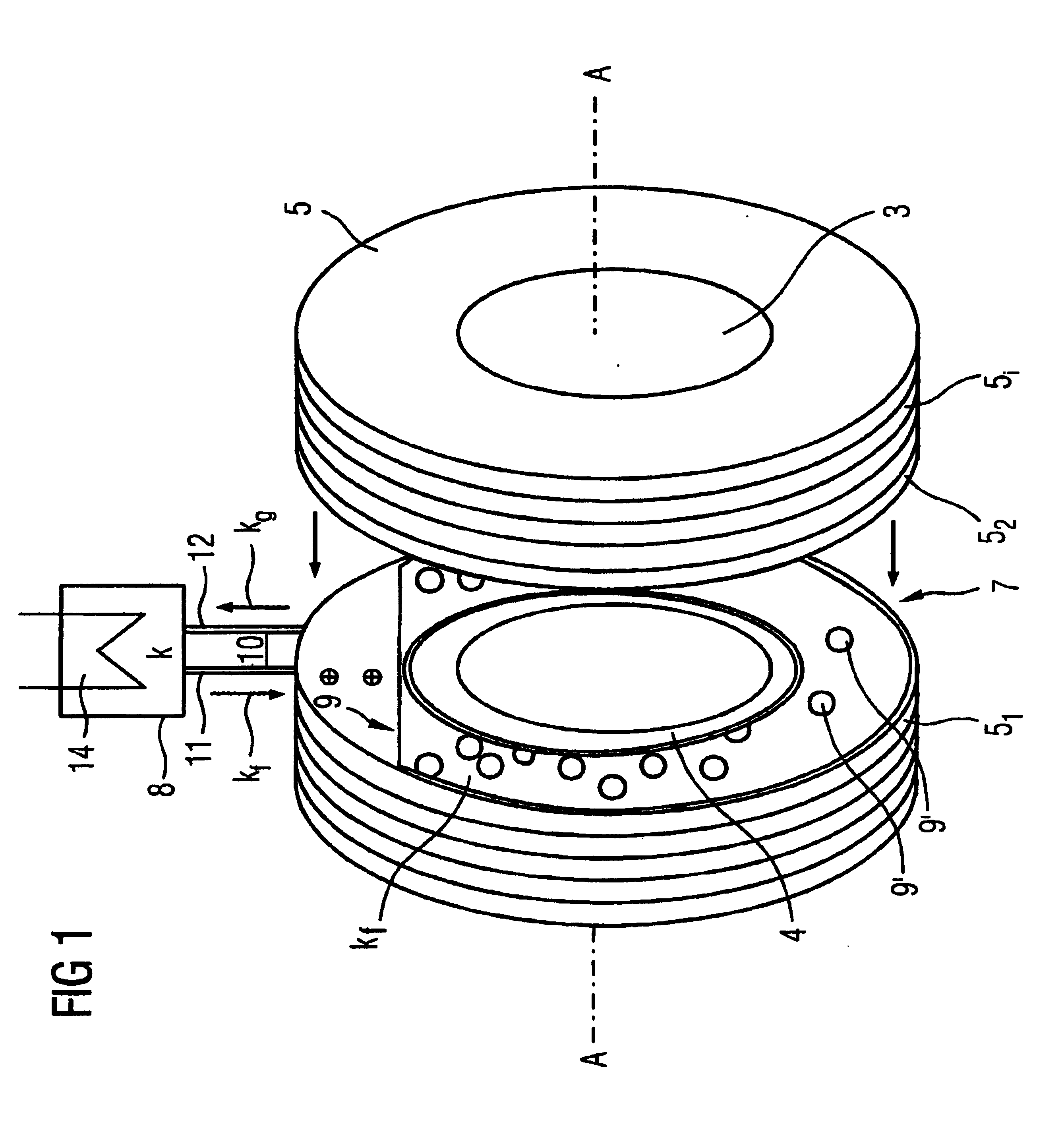
[0034] According to FIG. 1, the machine 2 has a cooled or uncooled rotor 3, which is mounted such that it can rotate about an axis A. The rotor is at least partially surrounded by a stator 5 while maintaining an intermediate space 4 with an annular cross section, of which stator 5 in FIG. 1 illustrates only individual laminates 5i of a laminated core. A coolant area 7 in the form of a disk is formed between two of these laminates 51 and 52, which are in the form o...


PUM


Abstract

A fixed stator is arranged around a rotatably mounted rotor in an electric motor that includes at least one cooling unit to which parts of the stator which are to be cooled are thermally coupled by a line system in which a cooling agent circulates according to a thermosyphon effect. The stator parts to be cooled can be arranged in the inner region of a stator housing which is integrated into the line system. The electric motor can be provided with a heating device to maintain the pressure in the inner region when the motor is stopped.

Description

[0001] This application is based on and hereby claims priority to German Application No. PCT / DE03 / 01705 filed on May 26, 2003 and German Patent Applications 102252224.6 filed Jun. 6, 2002 and 10317967.4 filed Apr. 17, 2003, the contents of all of which are hereby incorporated by reference. BACKGROUND OF THE INVENTION [0002] 1. Field of the Invention [0003] The invention relates to an electrical machine having] a rotor which is mounted such that it can rotate,] an associated, stationary stator, and] a device for cooling at least the stator or parts of it. [0004] 2. Description of the Related Art [0005] A corresponding machine is disclosed in EP 0 853 370 A1. [0006] A considerable amount of heat may be developed in the stator of machines or motors, particularly with relatively high power levels, and this has to be dissipated by cooling measures in order to achieve higher machine efficiency. By way of example, air-cooled generators (in particular with ratings below 300 MVA) are known, ...

Claims


Application Information

Patent Timeline
Patent Type & Authority Applications(United States)
IPC IPC(8): F28D15/02H02K9/19
CPCF28D15/0266H02K15/125H02K5/203
Inventor GROMOLL, BERNDHUBER, NORBERT
Owner SIEMENS AG
Why Eureka
Try Eureka