
Automatic paper feed apparatus

a paper feed apparatus and automatic technology, applied in the direction of thin material processing, article separation, transportation and packaging, etc., can solve the problems of complicated high cost, and complicated operation of interposition of paper plates, so as to prevent paper from being discharged and simple construction

Inactive Publication Date: 2005-07-21
YUYAMA MFG CO LTD
View PDF8 Cites 3 Cited by
  • Summary
  • Abstract
  • Description
  • Claims
  • Application Information

AI Technical Summary

Benefits of technology

[0007] An object of the invention is to provide an automatic paper feed apparatus which can reliably prevent papers from being discharged in an overlapped state in spite of simple construction.
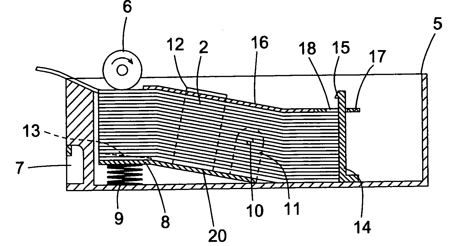
[0009] According to the above construction, when the paper positioned uppermost is conveyed by the paper feed roller, the holding member also comes into contact with the next paper to generate a friction force, preventing the next paper from being conveyed together with the uppermost paper. As the holding member has a flexibility itself, it surely comes into close contact with the paper along the surface of the paper and generates a uniform friction force, properly preventing any trouble of paper feed caused by the paper feed roller.
[0011] According to the above construction, when the paper feed roller rotates, the paper positioned uppermost commences moving due to a friction force between the paper and the paper feed roller. Since the uppermost paper moves together with the holding member put thereon, it is possible to generate a proper friction force between the paper feed roller and the paper. Therefore, smooth conveyance of the paper is made possible.
[0012] Even if the paper is a medicine bag and has a different thickness by location, the holding member becomes deformed along the surface of the medicine bags and the friction force to be generated becomes uniform, allowing the medicine bag to convey smoothly.

Problems solved by technology

Thus, there has been a disadvantage that it complicates the construction and invites cost up.
On the other hand, in the latter automatic paper feed apparatus, a complicated operation for interposing the plate between papers has been necessary.

Method used


Image

  • Automatic paper feed apparatus
  • Automatic paper feed apparatus
  • Automatic paper feed apparatus

Examples


Embodiment Construction

[0023] Hereinbelow, embodiments of the invention will be described with reference to the accompanying drawings.

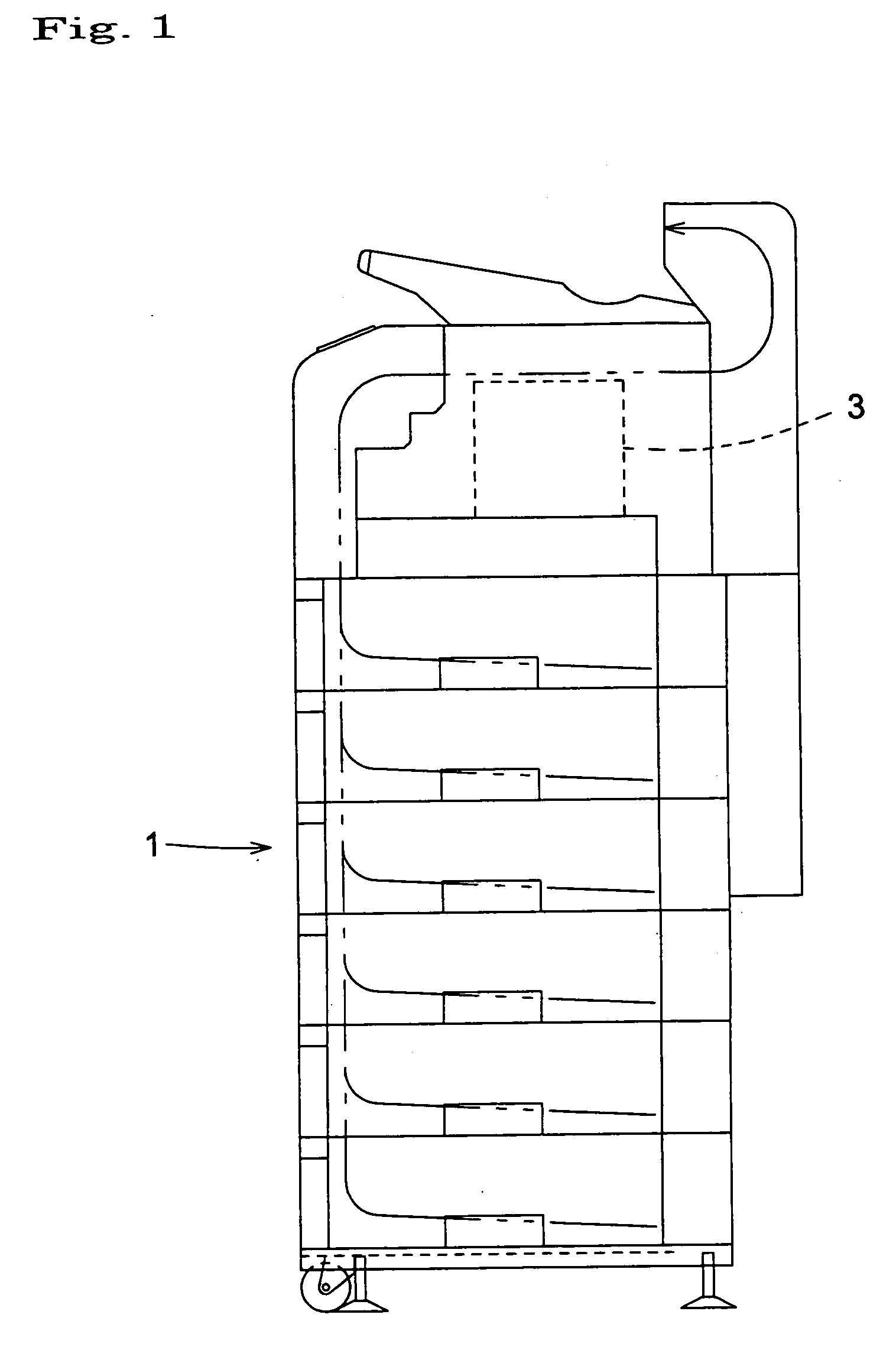
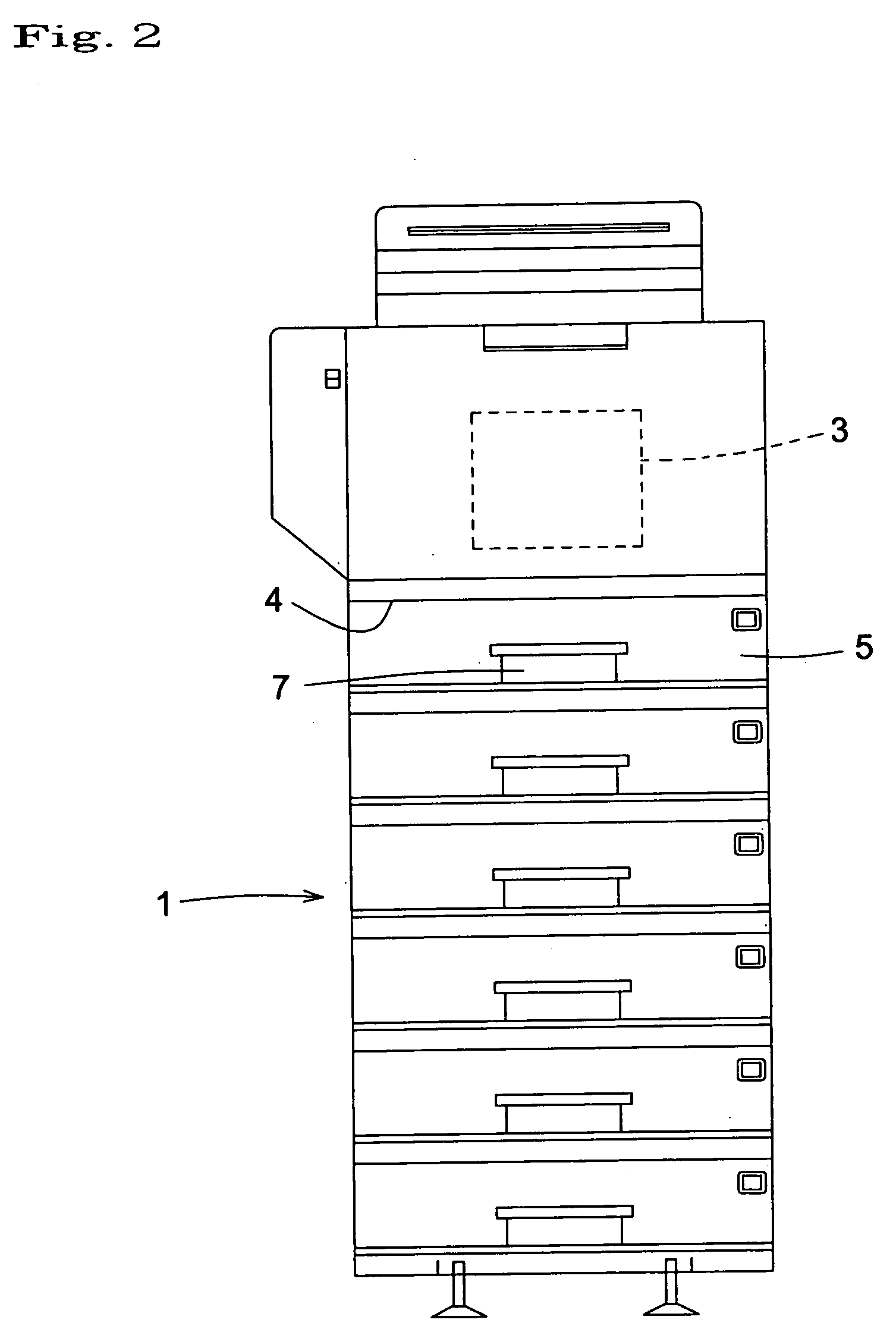
[0024]FIGS. 1 and 2 show a medicine bag printing apparatus according to an embodiment of the present invention. The medicine bag printing apparatus comprising an automatic paper feed apparatus 1 and a printing apparatus 3 for conducting a predetermined print on a paper 2 fed from the automatic paper feed apparatus 1. In this embodiment, a medicine bag (refer to FIG. 3) of which both side edges are stuck and become thick is used as a paper 2.

[0025] In the automatic paper feed apparatus 1, a cassettes 5 can be mounted into and dismounted from each of housing spaces 4 formed in multistage in a vertical direction. As shown in FIG. 5, in each housing space 4 is provided a paper feed roller 6 which is driven to rotate by drive means such as motor not shown. The paper feed roller 6 comes into contact with the paper 2 contained in the cassette 5 and positioned uppermost so that t...


PUM


Abstract

The present invention provides an automatic paper feed apparatus which can reliably prevent papers from being discharged in an overlapped state in spite of simple construction. The automatic paper feed apparatus comprises a paper feed roller for automatically feeding a plurality of papers in order from an uppermost one, with the plurality of papers being contained in a cassette in a stacked state. A holding member having flexibility is provided so that the holding member comes into contact with the uppermost paper to generate a friction force that is weaker than that between the paper feed roller and the uppermost paper.

Description

BACKGROUND OF THE INVENTION [0001] The present invention relates to an automatic paper feed apparatus for paper, especially medicine bag. [0002] Conventionally, an automatic paper feed apparatus having, for example, following construction has been known. [0003] Japanese Laid-open patent publication No. 49-67620 discloses an automatic paper feed apparatus in which a brake piece is provided on one end portion of copy papers stacked on the paper feed table to prevent the two copy papers from being conveyed at a time. [0004] Japanese Laid-open patent publication No. 58-69645 discloses an automatic paper feed apparatus in which plates are interposed between stacked papers. The friction coefficient between each plate and paper is smaller than that between papers, preventing the papers from being fed in an overlapped state. [0005] In the former automatic paper feed apparatus, the brake piece have to be provided on each copy paper. In addition, a solenoid and so on is necessary to lift the ...

Claims


Application Information

Patent Timeline
IPC IPC(8): B65H3/54B65H1/04B65H1/08B65H1/12B65H3/06B65H3/32B65H3/34B65H3/52B65H5/06
CPCB65H1/12B65H3/5215B65H3/06
Inventor TAKEDA, KENICHIIDE, YOSHIHIKO
Owner YUYAMA MFG CO LTD
Learn More