Vertical moulding of concrete

Inactive Publication Date: 2005-07-21
VERTECH HUME
View PDF2 Cites 12 Cited by
  • Summary
  • Abstract
  • Description
  • Claims
  • Application Information

AI Technical Summary

Benefits of technology

[0007] Accordingly the present invention provides a method of moulding long concrete articles in a vertical mould which incorporates a mould liner having drainage tubes used to dewater the concrete when the mould is filled, the improvement being to close off the drainage tubes during the filling of the mould to inhibit water loss in the concrete during filling.
[0012] d) preventing water from leaving the drainage tubes during the step of filling the mould with wet concrete
[0018] h) means associated with said drainage tubes to prevent water leaving said drainage tubes during the filling of the mould cavity
[0021] Another alternative is to use a thin flexible inner tube in side the drainage tubes which inner tube can be pressurized with air or fluid to press against the openings in the drainage tubes to prevent water escaping from the concrete. When the inner tube is depressurized, water can escape to allow dewatering of the concrete in the filled mould.

Problems solved by technology

Although these methods produce poles of adequate strength the surface finish of the articles is sometimes rough and cavities form in the surface during stripping of the article from the mould.
The dewatering step also appears to proceed unevenly in the moulded product.

Method used


Image

  • Vertical moulding of concrete
  • Vertical moulding of concrete
  • Vertical moulding of concrete

Examples


first embodiment

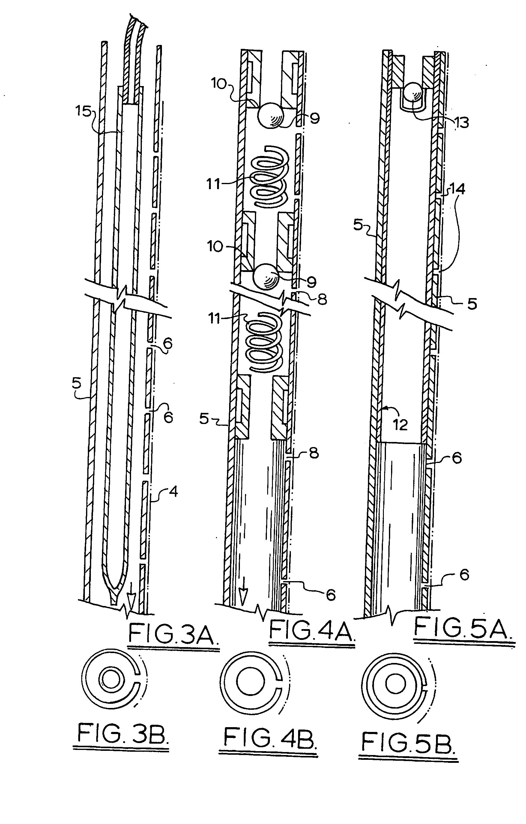
[0025]FIGS. 3A (cross section) and 3B (plan view) is a schematic illustration of the drainage tube of this invention;

second embodiment

[0026]FIGS. 4A (cross section) and 4B (plan view) is a schematic illustration of the drainage tube of this invention;

third embodiment

[0027]FIGS. 5A (cross section) and 5B (plan view) is a schematic illustration of the drainage tube of this invention;

[0028] FIGS. 6 (cross section) and 7 (plan view) illustrate a test rig used to determine the effectiveness of the water control method of this invention.

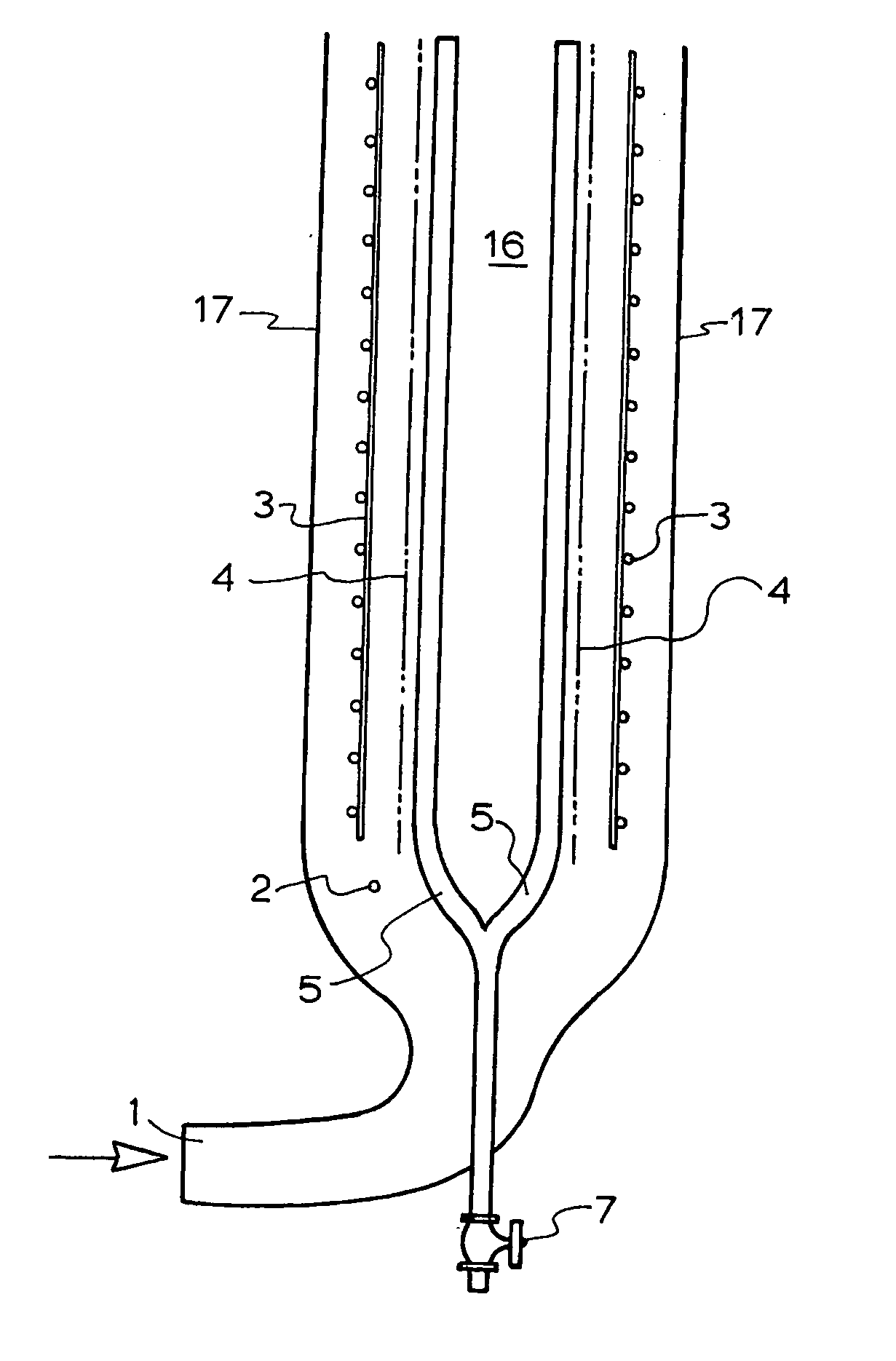
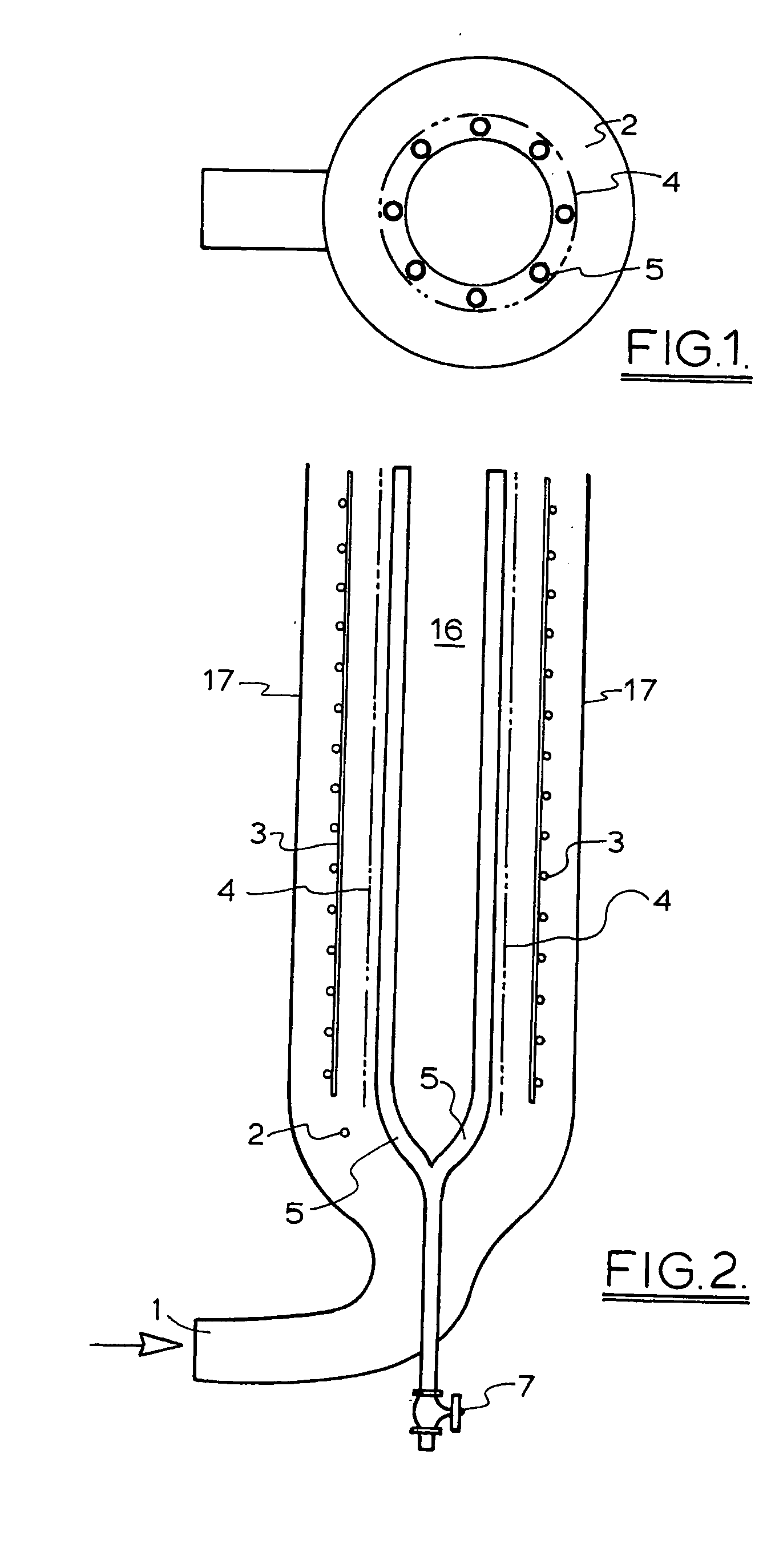
[0029] The vertical mould for forming concrete poles is of the kind described in U.S. Pat. No. 6,284,172 the contents of which are incorporated herein by reference. The difference is that the drainage tubes in the filter media of the mould liner are modified in accordance with this invention. The mould is usually 12.5 metres high and concrete in a water / cement ration of about 0.45 is pumped into the bottom of the mould. Once the concrete comes into contact with the filter media water begins to bleed into the drainage holes which are usually spaced at 50 mm centres. The pressure required to raise the concrete 12.5 metres is approximately 830 kPa but varies with the water to cement ratio, the aggregate used and the com...


PUM

PropertyMeasurementUnit
Pressureaaaaaaaaaa
Viscosityaaaaaaaaaa

Abstract

A method of moulding long concrete articles in a vertical mould which incorporates a mould liner (17) with drainage tubes (5) used to dewater the concrete when the mould is filled. The improvement is to close off the drainage tubes (5) during the filling of the mould to inhibit water loss in the concrete during filling. The drainage tubes (5) may incorporate one way valves or include inner tubes (15) that may be pressurized to inhibit water entering the drainage tube (5).

Description

[0001] This invention relates to improvements in the moulding of concrete articles such as poles, piles or pipes in a vertical mould. BACKGROUND TO THE INVENTION [0002] The moulding of concrete pipes, hollow poles or piles in a vertical mould has been proposed in U.S. Pat. No. 4,996,013. The mould is filled from the bottom and the concrete is compressed between an inner and outer mould by moving the inner mould outwardly using a flexible membrane. Water drained from the concrete into drainage galleries or tubes in the membrane. Because water segregates from the concrete during the filling of the mould water tended to accumulate in the upper section of the mould during filling. This problem was addressed in U.S. Pat. No. 6,284,172 by capping the end of the mould to allow egress of fluid but retain particulates and stopping the filling of the mould when the presence of solid materials at the end cap is sensed. [0003] Although these methods produce poles of adequate strength the surfac...

Claims


Application Information

Patent Timeline
IPC IPC(8): B28B7/46B28B21/38
CPCB28B21/38B28B7/46
Inventor HUME, GRAEME R
Owner VERTECH HUME
Why Eureka
Try Eureka