Preparation of capsules

a technology of capsules and encapsulation processes, applied in colloidal chemistry, packaged goods types, instruments, etc., can solve the problems of inadequate service life of these displays, and low yield of capsules with the desired diameter rang

Inactive Publication Date: 2005-07-21
E INK CORPORATION
View PDF99 Cites 199 Cited by
  • Summary
  • Abstract
  • Description
  • Claims
  • Application Information

AI Technical Summary

Benefits of technology

[0028] emulsifying the water-immiscible phase in the aqueous medium comprising the coacervate under conditions effective to cause deposition of the coacervate around the water-immiscible phase, thereby forming capsules of the water-immiscible phase surrounded by capsule walls of the coacervate.

Problems solved by technology

Nevertheless, problems with the long-term image quality of electrophoretic displays have prevented their widespread usage.
For example, particles that make up electrophoretic displays tend to settle, resulting in inadequate service-life for these displays.
Also, when such an electrophoretic medium is produced by coating capsules on to a substrate, it is desirable that the exposed surface of the capsule layer be reasonably flat, since otherwise difficulties may be encountered in laminating the capsule layer to other layers in the final display.
Unfortunately, it has been found that the prior art encapsulation process described above does not produce a high yield of capsules with the desired range of diameters.
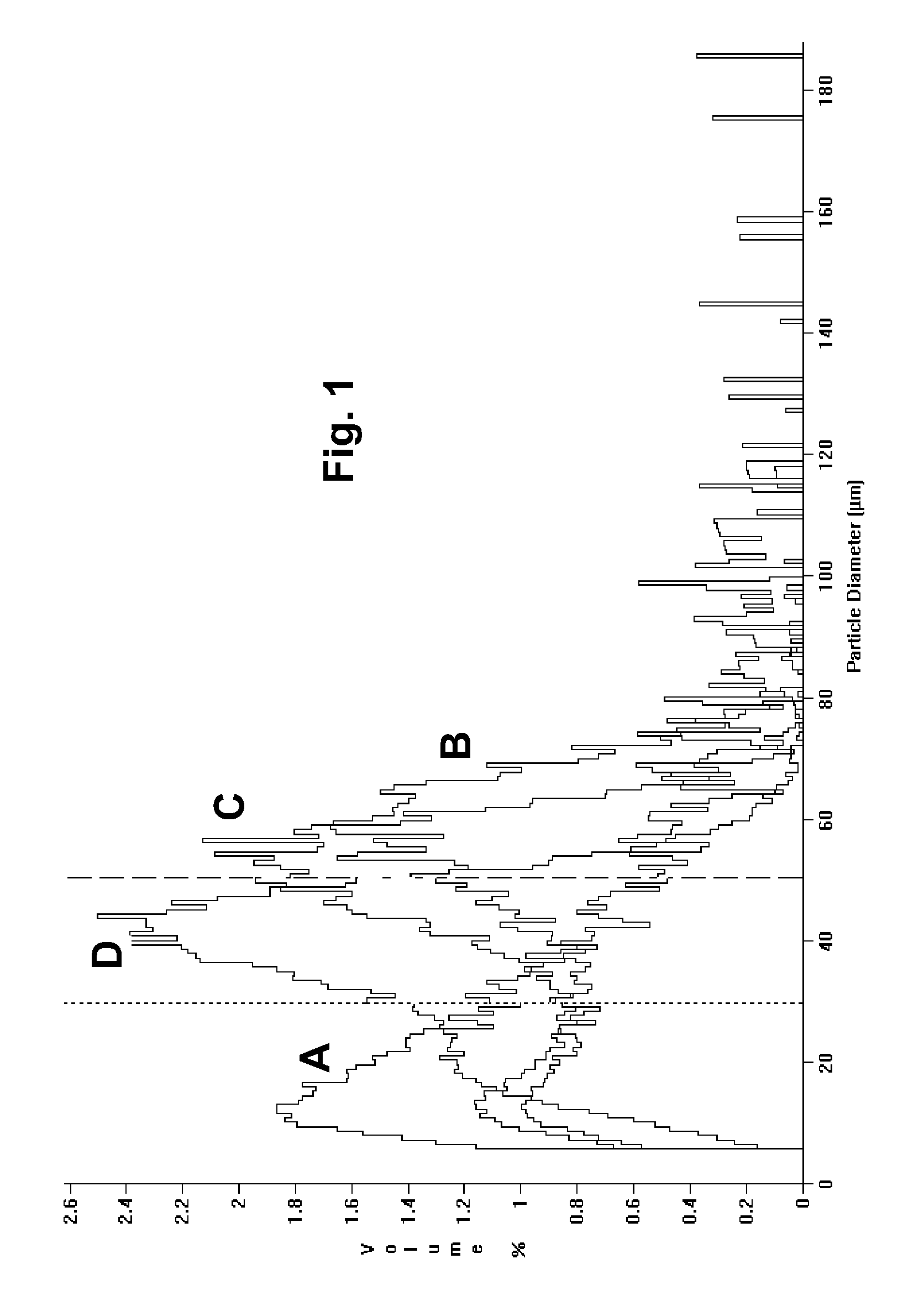
Although the average capsule diameter can be varied over a considerable range by controlling parameters such as gelatin concentration, stirring rate, etc., it has not proved possible to increase yields above this range, the major problem being the high proportion of “fines” or capsules having diameters below the acceptable range; for example, as shown in the Example below, in a typical optimized prior art process designed to produce 30-50 μm capsules, the volume percent capsules actually peaks at about 10-12 μm.
Obviously such low yields of useful capsules are a major problem, since they greatly increase the cost of the electrophoretic medium and generate substantial costs for disposing of the unacceptable capsules.
The prior art process is also not easily scalable, requiring re-optimization each time the size and / or shape of the reactor is changed.
If too little promoter is present, the surface-active particulate material will not adsorb at the oil-water interface, and the oil droplets will not acquire stability; however, if too much promoter is present, the surface-active particulate material will either coagulate and separate from the suspension, or partition into the oil phase.
In each of these cases, the result is failure of the limited coalescence process, which requires the formation of a stable Pickering emulsion.
This emulsion is unstable, because the small size of the particles makes the oil-water interfacial area very much larger than that which can be covered by the limited amount of surface-active particulate material present.
As already mentioned, limited coalescence processes have primarily been developed for the preparation of droplets of monomer for use in suspension polymerization processes, and there are a number of problems with applying such processes in other contexts.
Secondly, the oil-in-water emulsion formed during homogenization must be unstable with respect to coalescence, and this requires that any surfactants already present in the system must be rendered ineffective.

Method used


Image

  • Preparation of capsules
  • Preparation of capsules
  • Preparation of capsules

Examples


example 1

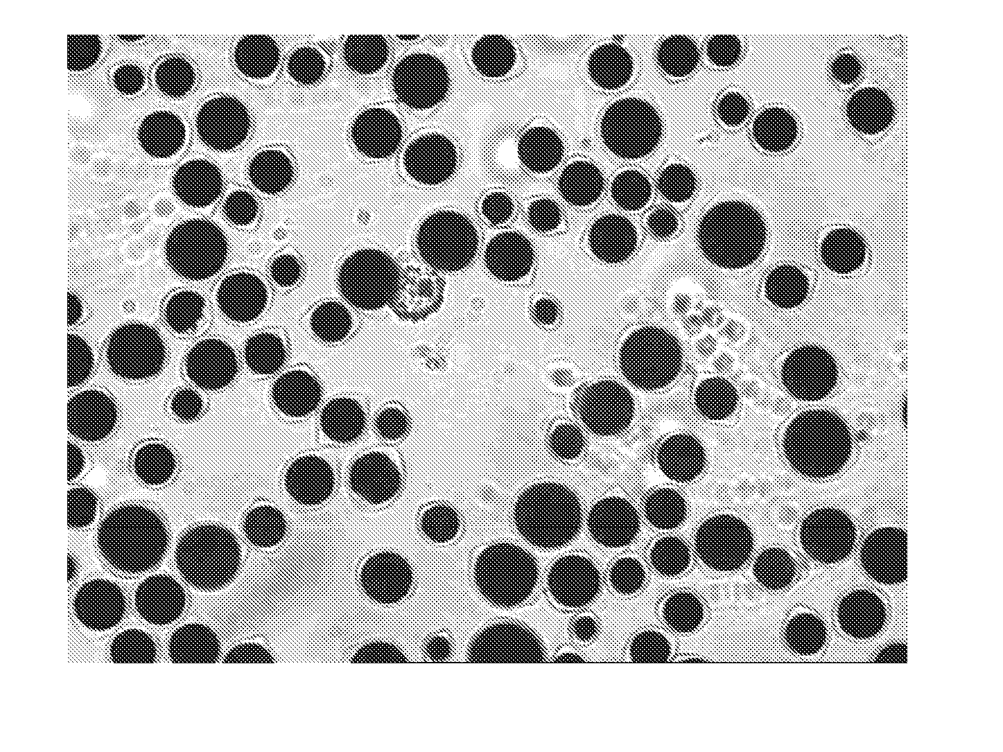
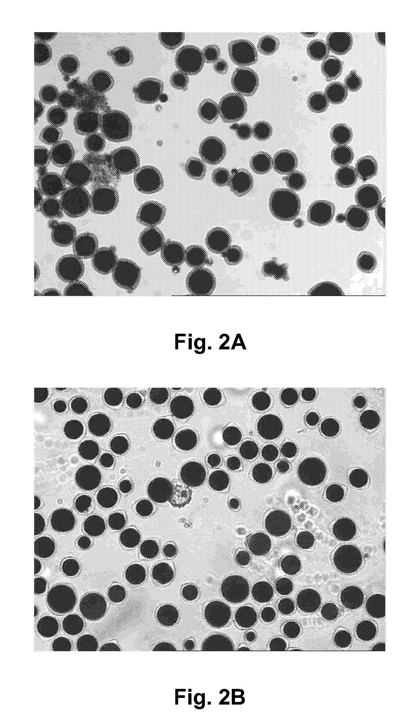
[0055] An internal phase was prepared substantially as described in the aforementioned 2002 / 0180687, this internal phase comprising polymer-coated titania and polymer-coated carbon black in a hydrocarbon solvent. This internal phase was then encapsulated by both a prior art (“PA”) process and a preformed coacervate process (“PC”) of the present invention. The material amounts given for the PC process are for a scaled down volume of 75%, based on water and oil amounts, of the original PA process. The material and amounts used for the two encapsulations were are shown in Table 1 below:

TABLE 1MaterialPAPCDeionized water3277618437Gelatin667300Makeup water06145Acacia667300Internal Phase107008025Glutaraldehyde16787.7

[0056] The encapsulations were performed in a 50 L reactor provided with a propeller type stirrer. The prior art process was carried out substantially as described in the aforementioned 2002 / 0180687. The gelatin was added to the deionized water in the reactor and the mixture...

example 2

[0071] Two identical internal phases were prepared each comprising 42.5 g of a 60 weight percent suspension of a polymer-coated copper chromite pigment in Isopar E (a hydrocarbon solvent available from Exxon Corporation, Houston Tx.; ISOPAR is a Registered Trade Mark), 85 g of a 60 weight percent suspension of a polymer-coated titania pigment in Isopar E, 10.71 g of a solution of Solsperse 17K in Isopar G (a hydrocarbon solvent from the same manufacturer as Isopar E), 0.77 g of Span 80 (a surfactant available from Aldrich Chemical Corporation), and 31.03 g of additional Isopar E.

[0072] One of internal phases was used in a control experiment using a prior art encapsulation process substantially as described in the aforementioned 2002 / 0180687. The emulsification step was carried out by addition of the 140 mL internal phase to a solution of 10 g of gelatin in 240 g water at 42.5° C., and agitating the resulting mixture with a 2 inch (51 mm) prop impeller at 650 rpm for one hour. By th...


PUM

PropertyMeasurementUnit
temperatureaaaaaaaaaa

Abstract

Prior art processes for producing protein-based capsules (for example, capsules for use in electrophoretic media) tend to be wasteful because they produce many capsules outside the desired size range, which is typically about 20 to 50 μm. Capsule size distribution and yields can be improved by either (a) emulsifying a water-immiscible phase in a preformed coacervate of the protein; or (b) using a limited coalescence process with colloidal alumina as the surface-active particulate material.

Description

REFERENCE TO RELATED APPLICATIONS [0001] This application claims benefit of Provisional Application Ser. No. 60 / 481,920, filed Jan. 20, 2004, and Provisional Application Ser. No. 60 / 521,010, filed Feb. 5, 2004. [0002] The entire disclosures of these two applications, and of all U.S. patents and published and copending applications referred to below are also herein incorporated by reference.BACKGROUND OF INVENTION [0003] This invention relates to the preparation of capsules, especially capsules intended for use in forming electrophoretic media. [0004] Particle-based electrophoretic displays, in which a plurality of charged particles move through a suspending fluid under the influence of an electric field, have been the subject of intense research and development for a number of years. Such displays can have attributes of good brightness and contrast, wide viewing angles, state bistability, and low power consumption when compared with liquid crystal displays. [0005] (The terms “bistab...

Claims


Application Information

Patent Timeline
Patent Type & Authority Applications(United States)
IPC IPC(8): B01J13/08B65B1/00G02F1/167
CPCG02F1/167B01J13/08Y10T428/2982Y10T428/2984Y10T428/2991Y10T428/2998
Inventor VALIANATOS, PETER J.CHEBIYAM, RAJESHMANNING, JEREMY J.STEINER, MICHAEL L.WHITESIDES, THOMAS H.WALLS, MICHAEL D.
Owner E INK CORPORATION
Why Eureka
Try Eureka