
Manual breast pump

a breast pump and manual technology, applied in the field of manual breast pump, can solve the problems of inaccurate and inefficient simulation of the way a baby is suckling, many contemporary devices also do not separate the air in the vacuum system from the air in the breast cup, and reduce or eliminate the risk of breast milk contamination. , the effect of increasing comfor

Inactive Publication Date: 2005-07-14
PLAYTEX PROD INC
View PDF99 Cites 190 Cited by
  • Summary
  • Abstract
  • Description
  • Claims
  • Application Information

AI Technical Summary

Benefits of technology

[0011] Another object of the present invention is to provide the breast pump with a barrier or isolation member that separates the breast from the vacuum system, thereby reducing or eliminating the risk of contamination of the breast milk.
[0012] A further object of the present invention is to provide the user of the breast pump with handles that increase comfort when using the breast pump.
[0013] A still further object of the present invention is to provide an inverted manual pump handle that is better suited to the characteristics of a female user's hand.
[0025] The handle to be manipulated by the user extends upward from the chamber, providing an easy way for the user to grip the handle. The handle is pulled toward the breast cup and released to create negative and positive pressure in the chamber. The body of the handle can be made of a stiff plastic to provide support, and the grip can be made from a softer plastic for an easier grip.

Problems solved by technology

Conventional devices suffer from several drawbacks.
This is an inaccurate and inefficient simulation of the way a suckling baby feeds.
Many contemporary devices also do not separate the air in the vacuum system from the air in the breast cup.
This potentially would allow the milk to enter the pump mechanism, causing damage to the system and unwanted cleanup.
The contemporary manual pump systems have pump handles that are not ergonomically designed to fit a woman's hand.
The handles slope away from the breast cup and require the woman to extend her hand in an uncomfortable manner.
Over repeated cycles of pumping, such designs can result in prolonged pain to the user's hand.
Contemporary manual pumps often require that the pump mechanism be connected to the breast cup, which may be uncomfortable and tiresome for the user.
Contemporary manual breast pump systems further fail to facilitate cleaning of the devices through use of easily separable components.

Method used


Image

  • Manual breast pump
  • Manual breast pump
  • Manual breast pump

Examples


Embodiment Construction

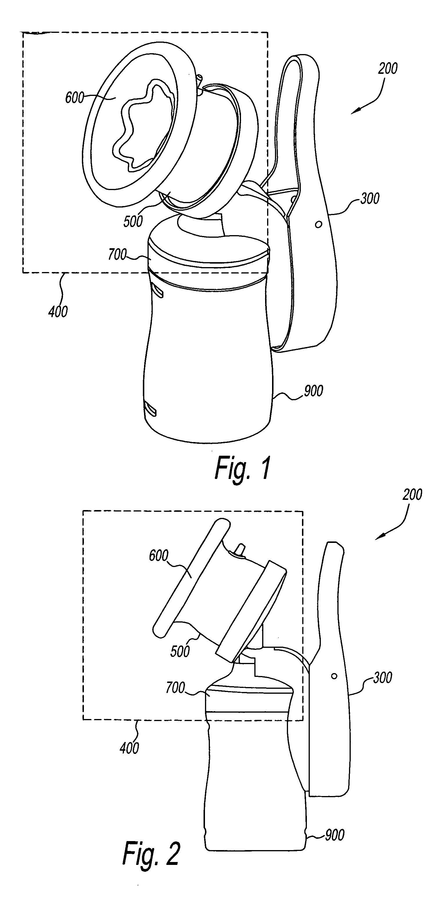
[0044] Referring to the drawings and in particular FIGS. 1 through 3, there is shown a preferred embodiment of a breast pump generally referred to by reference number 200. The breast pump 200 has a pump mechanism 300, a breast cup 400 and container 900.

[0045] Breast cup 400 has a housing 500, a flexible insert 600, a holder 700 and a one way valve 800 (shown in FIG. 3). Referring to FIG. 3, pump mechanism 300 has a handle 320, an actuator 340, a chamber diaphragm 360, and a holder attachment or diaphragm housing 380.

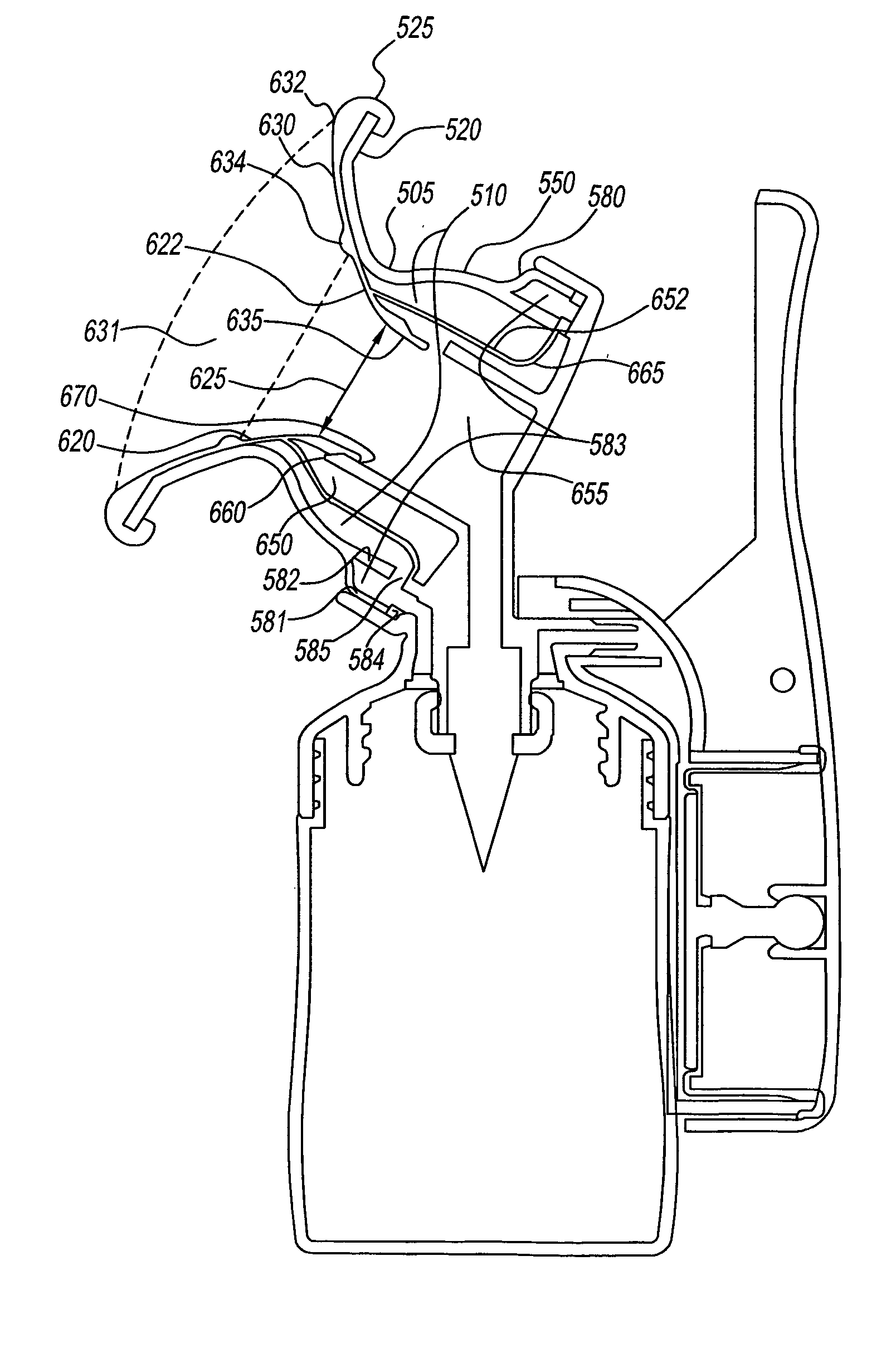
[0046] Referring to FIGS. 1 through 4, housing 500 is preferably a rigid or substantially rigid structure formed by a circumferential wall 505 defining a housing volume 510. Circumferential wall 505 preferably has a funnel shape with a generally hour-glass-shaped cross-section. Housing 500 has an outer section 520, a middle section 550 and an inner section 580. In this embodiment, outer section 520 generally has a diameter that is larger than the diameters of middle se...


PUM


Abstract

A manually actuated breast pump is provided. The breast pump has a breast cup, pump mechanism and a container. The components of the breast pump are easily assembled and disassembled to facilitate use, cleaning, manufacture and transport. The breast pump can apply a negative pressure, a positive pressure or both to a user's breast. The breast pump provides fluid isolation between the pressure source and the expressed milk.

Description

RELATED APPLICATION [0001] This application is a continuation-in-part of copending U.S. application Ser. No. 10 / 637,979, filed Aug. 8, 2003, the disclosure of which is incorporated by reference herein in its entirety.BACKGROUND OF THE INVENTION [0002] 1. Field of the Invention [0003] The present invention relates to devices and methods to obtain breast milk. More particularly, the present invention relates to a device and method for expressing breast milk through use of a breast cup and manual pump. [0004] 2. Description of the Related Art [0005] Breast pump systems that use either manual or automatic means for obtaining breast milk are known in the art. Typically, these systems use a vacuum source to generate a negative pressure through a hood or cup that is applied to the breast. Contemporary automated breast pumps typically use separate breast receiving portions and pump mechanisms by applying the vacuum pressure through tubing or conduit connected therebetween. [0006] Convention...

Claims


Application Information

Patent Timeline
Patent Type & Authority Applications(United States)
IPC IPC(8): A61MA61M1/06
CPCA61M1/06A61M2205/071A61M1/066A61M1/064A61M1/0072A61M1/82A61M1/0697
Inventor RENZ, CHARLES J.NELSEN, DANIEL J.ROBSON, DAVIDPETRIE, AIDAN
Owner PLAYTEX PROD INC
Learn More