Ink-jet formation of flexographic printing plates

a technology of flexographic printing and inkjet, which is applied in the direction of photomechanical treatment, instruments, photosensitive materials, etc., can solve the problems of large droplets, high cost, and time-consuming of the above-described process, and achieve the effects of reducing production costs, reducing production costs, and reducing production costs

Inactive Publication Date: 2005-07-14
KODAK POLYCHROME GRAPHICS
View PDF29 Cites 68 Cited by
  • Summary
  • Abstract
  • Description
  • Claims
  • Application Information

AI Technical Summary

Benefits of technology

[0012] In one embodiment, the present invention provides a method for forming a relief image or pattern on a substrate, in which an image-forming material is imagewise ink-jet applied onto a surface of a substrate and then optionally treated to form the relief image or pattern. In this embodiment, the image-forming material may be applied using an electrophoretic ink-jet system capable of stacking or layering respective droplets of the image forming material. Suitable image-forming materials include non-conductive particles that are dispersed in a carrier. The relief image may be formed by a single layer of a sufficiently viscous image-forming material. Alternatively, the relief image may be formed by continuously stacking or layering droplets of the image-forming material. The method may also optionally utilize one or more drying or curing steps (such as by ultraviolet or infrared radiation) during application of the image-forming material, and / or after formation of the relief image. After forming the desired relief image, the relief image may also be treated to increase the ink receptiveness of the relief image.

Problems solved by technology

Unfortunately, the above-described process may be relatively costly, time consuming and / or require the use of caustic chemicals for development.
Each of these systems suffers from certain drawbacks.
However, such printing devices tend to produce larger droplets and are only able to eject a limited range of ink material.
Furthermore, neither system is capable of precisely depositing suitably sized droplets of a wide range of materials, particularly materials having a relatively high viscosity when compared to conventional ink-jettable materials.
Likewise, conventional ink-jet materials used with these systems suffer from several drawbacks, including problems relating to a lack of suitable adhesion to substrates, poor image resolution, low durability, and / or short press life.
One problem particular to the ink-jet formation of a relief image or pattern on a plate is that the oleophilic image must be raised above the substrate.
Unfortunately, conventional ink-jet materials lack the characteristics (e.g. viscosity, curability) required to form a raised image.

Method used


Image

  • Ink-jet formation of flexographic printing plates
  • Ink-jet formation of flexographic printing plates
  • Ink-jet formation of flexographic printing plates

Examples


Embodiment Construction

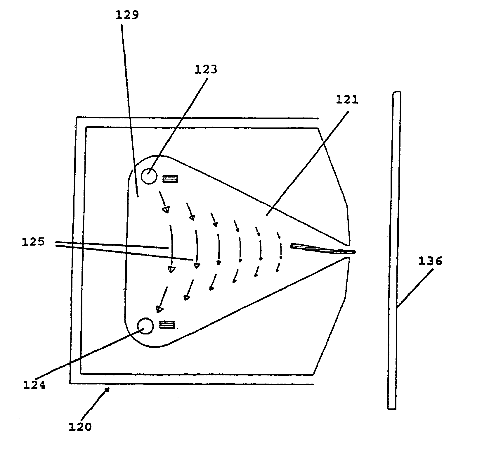
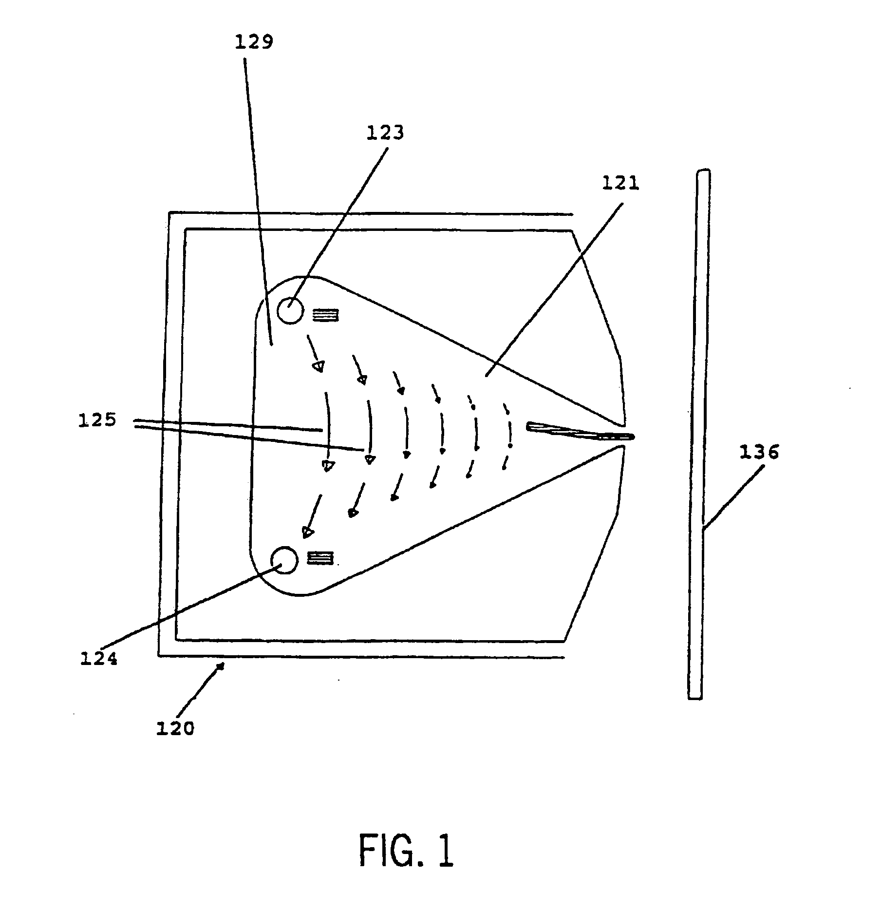
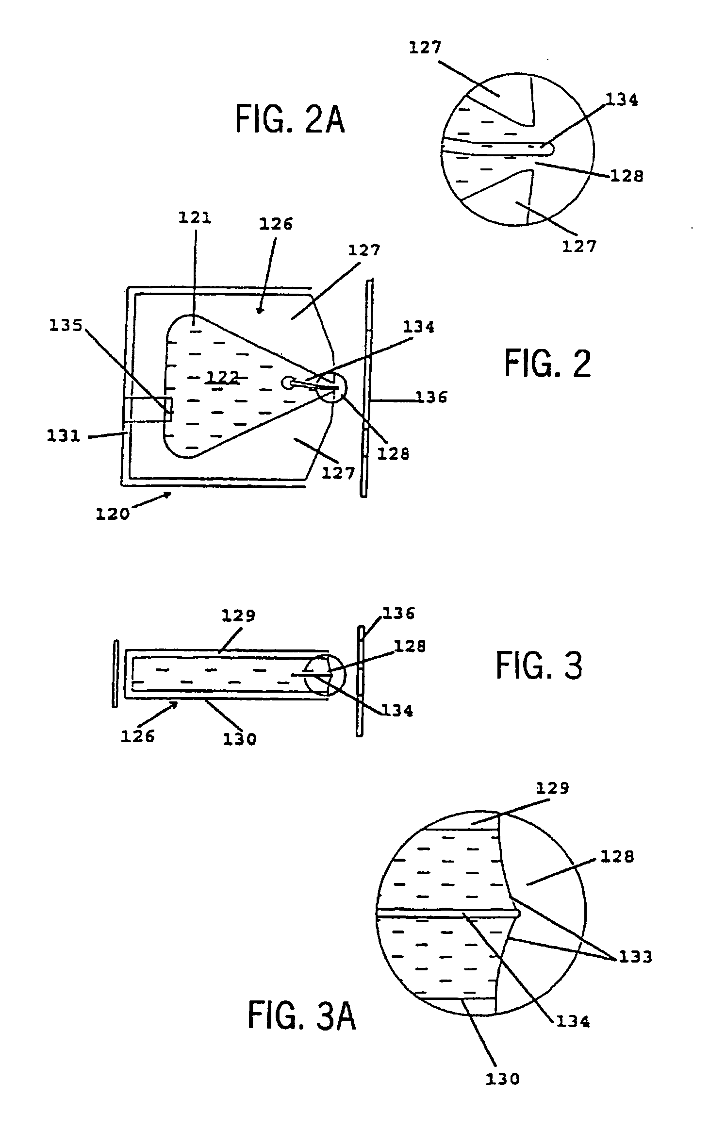
[0027] In one embodiment, the present invention provides methods for forming a relief image or pattern (collectively referred to herein as a “relief image”) on a substrate, which may be suitable for use in forming relief images for use in flexographic printing plates. As used herein, the term “relief image” refers to relief images such as those used in flexographic and letterpress applications, as well as other images or patterns that are formed on a substrate that have a significant topography or texture. To form the desired relief image, an optimized ink-jet system imagewise ejects an image-forming material directly onto a substrate. The image-forming material may then be further treated to form a relief image.

[0028] Suitable substrates for use with embodiments of the present invention include conventional substrates commonly used in conventional relief plate applications. Suitable substrates are generally strong, dimensionally stable, and flexible. Suitable substrates should res...


PUM


Abstract

The present invention provides a method for forming a flexographic printing plate that includes imagewise applying an image-forming material onto a substrate with an ink-jet printer to form a relief image, in which the image-forming material adheres to the surface of the substrate and resists deformation. The method of the present invention may further include treating the relief image.

Description

[0001] The present application claims the benefit of pending U.S. provisional patent application, Ser. No. 60 / 535,311, entitled INK-JET FORMATION OF FLEXOGRAPHIC PRINTING PLATES, filed on Jan. 9, 2004.BACKGROUND [0002] Relief printing plates are used in both flexographic and letterpress processes for printing on a variety of media, particularly for media which are soft and easily deformable, such as paper or plastic packaging materials, cardboard or other corrugated stock, film, foil, and laminates. Relief printing plates generally consist of raised image areas and depressed non-image areas. During printing, ink is transferred only from the raised image areas to the print media. [0003] Historically, relief printing plates such as flexographic printing plates were formed from vulcanized rubber. Rubber was favored because it is resistant to harsh solvents, it has good ink transfer characteristics, high elasticity, and high compressibility. Rubber printing elements were originally made...

Claims


Application Information

Patent Timeline
IPC IPC(8): B41C1/00
CPCB41C1/003
Inventor RUNDLE, MICHAEL STEPHENEDWARDS, DOUGLAS J.
Owner KODAK POLYCHROME GRAPHICS
Why Eureka
Try Eureka